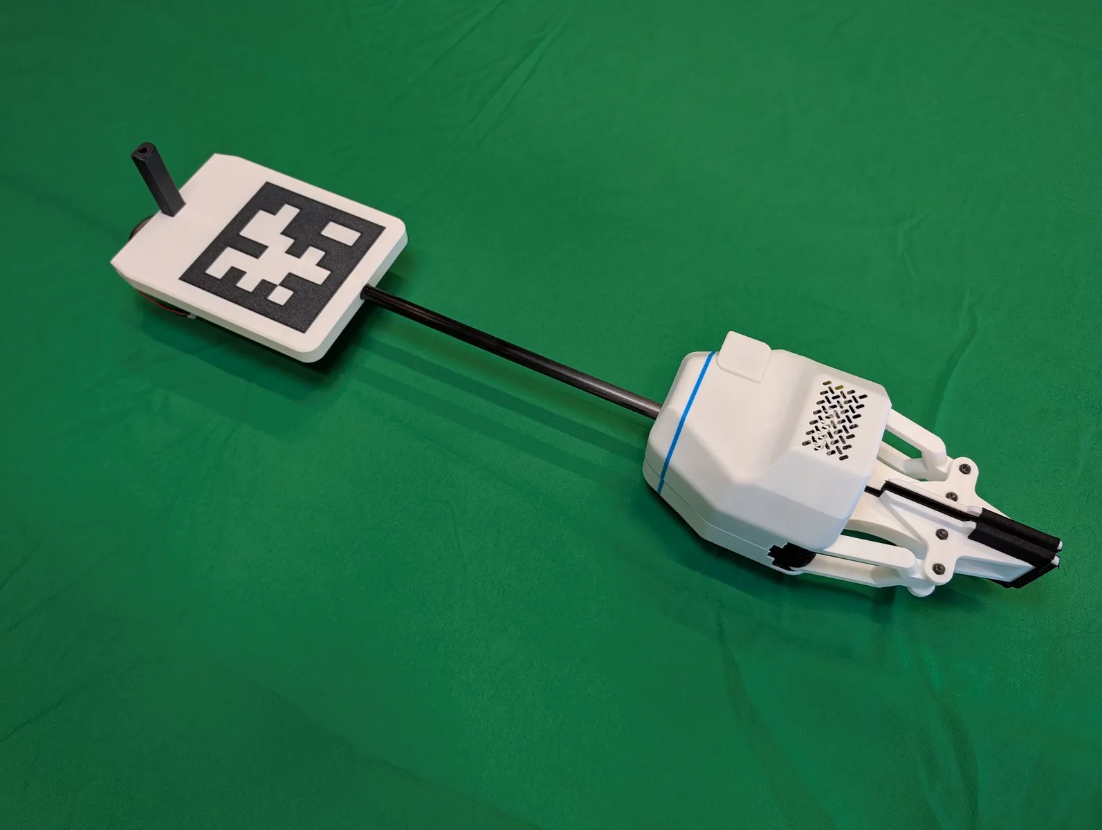
Arpeggio Gripper Build Guide
Hardware Version: Arpeggio
Print time: 20 hours
Build time: 2 hours
Resources
Tool list
- Mini screwdriver with a bit set. Manual or Electric
- Super glue (loctite super glue “professional liquid” recommended)
- exacto/hobby knife
- flush cut wire clippers
Soldering
Kits purchased from neufangled.com after Jun 26 2026 do no require any soldering. Kits earlier than that, or parts sourced yourself may require soldering.
Fingers
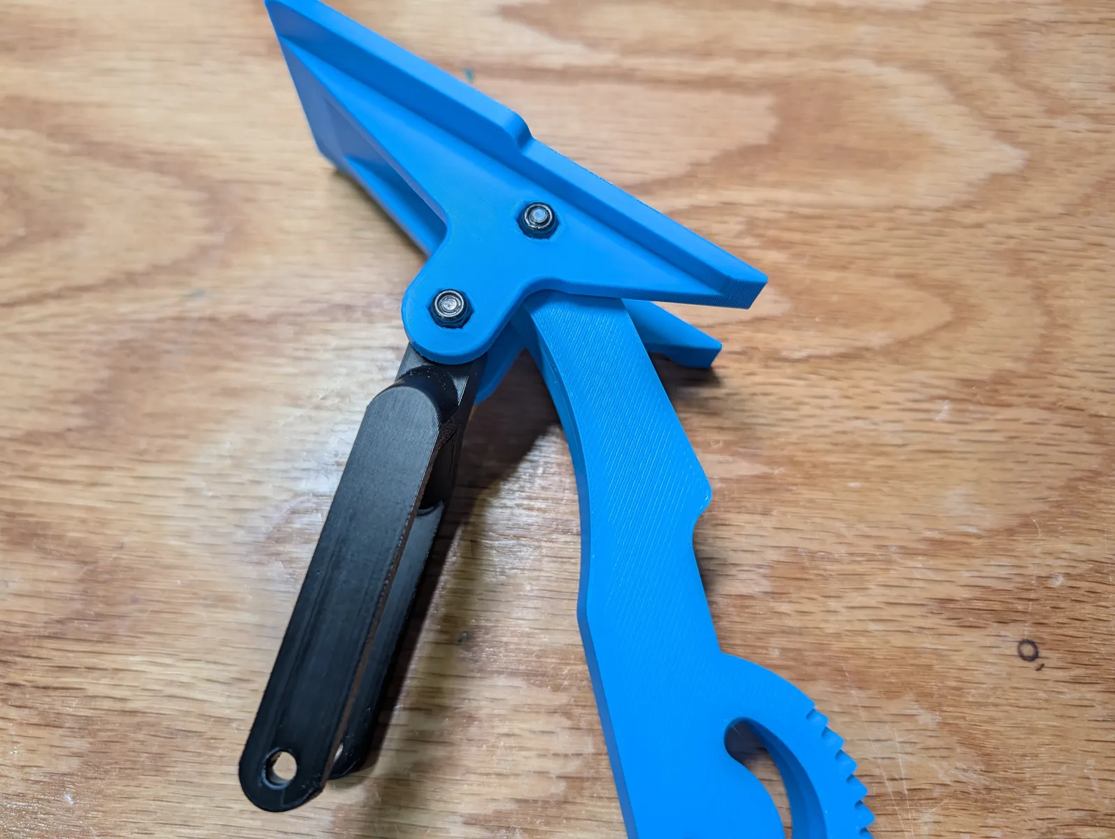
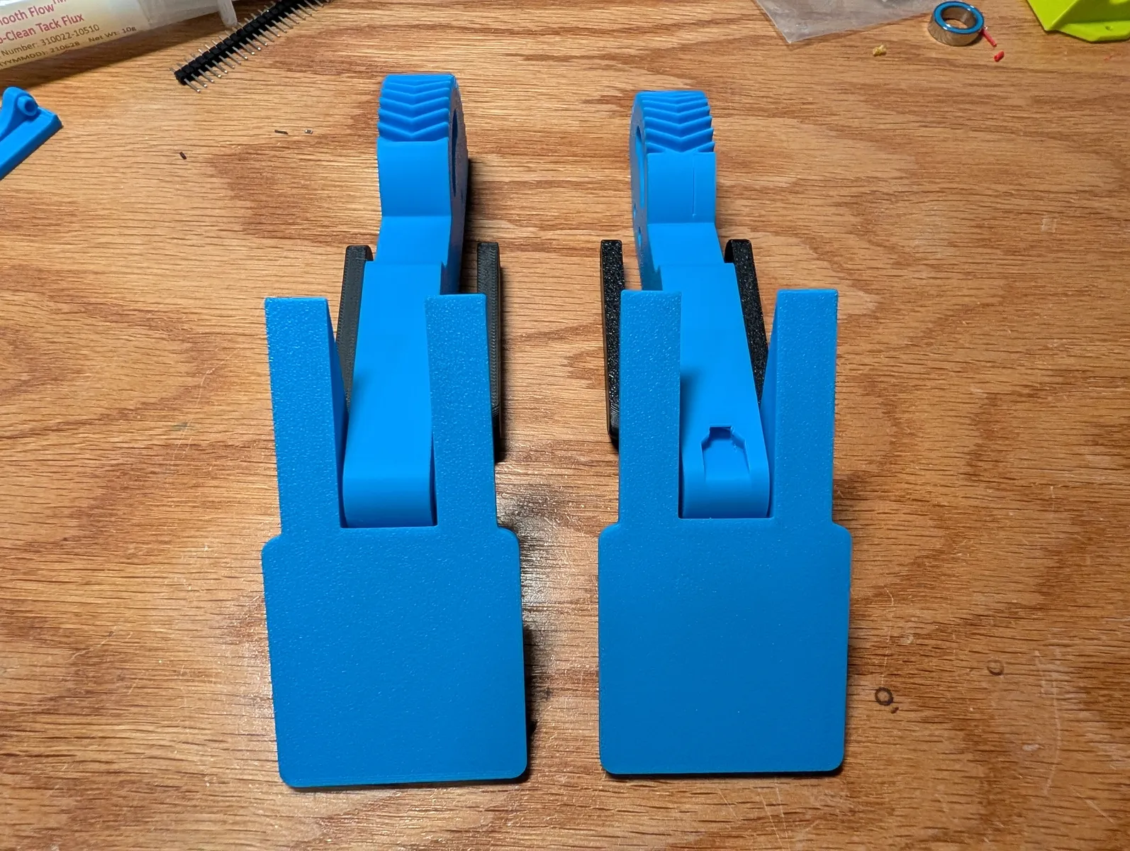
Attach a fork to the back of a finger pad. Forks and finger pads are both symmetrical. There is no left and right finger. Insert an M3x25 bolt through the upper hole, passing through both parts, followed by an M3 lock nut on the other side. Tighten the nylock nut until no slack remains, then back off until the rod can swing. Repeat for the other finger.

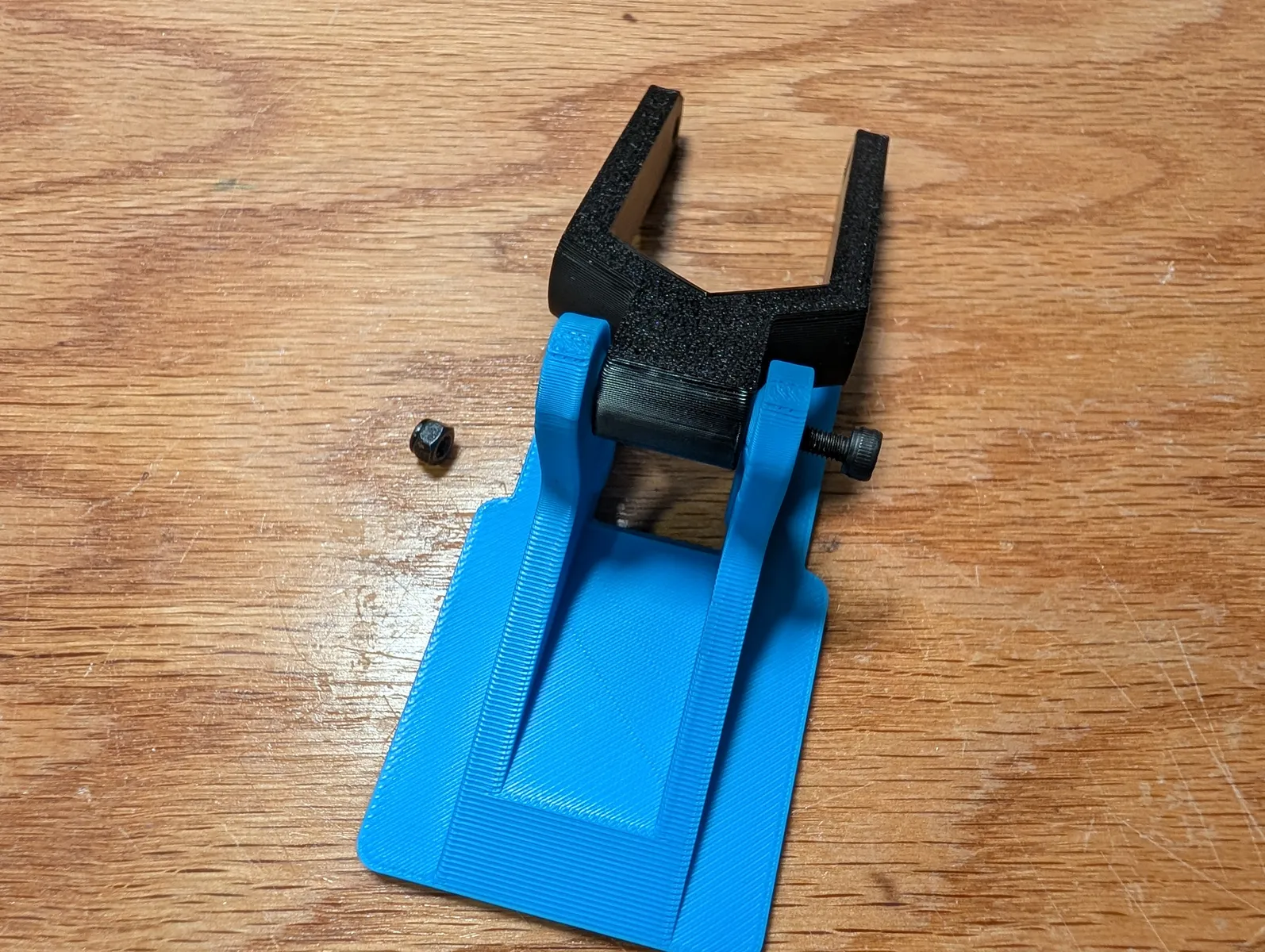
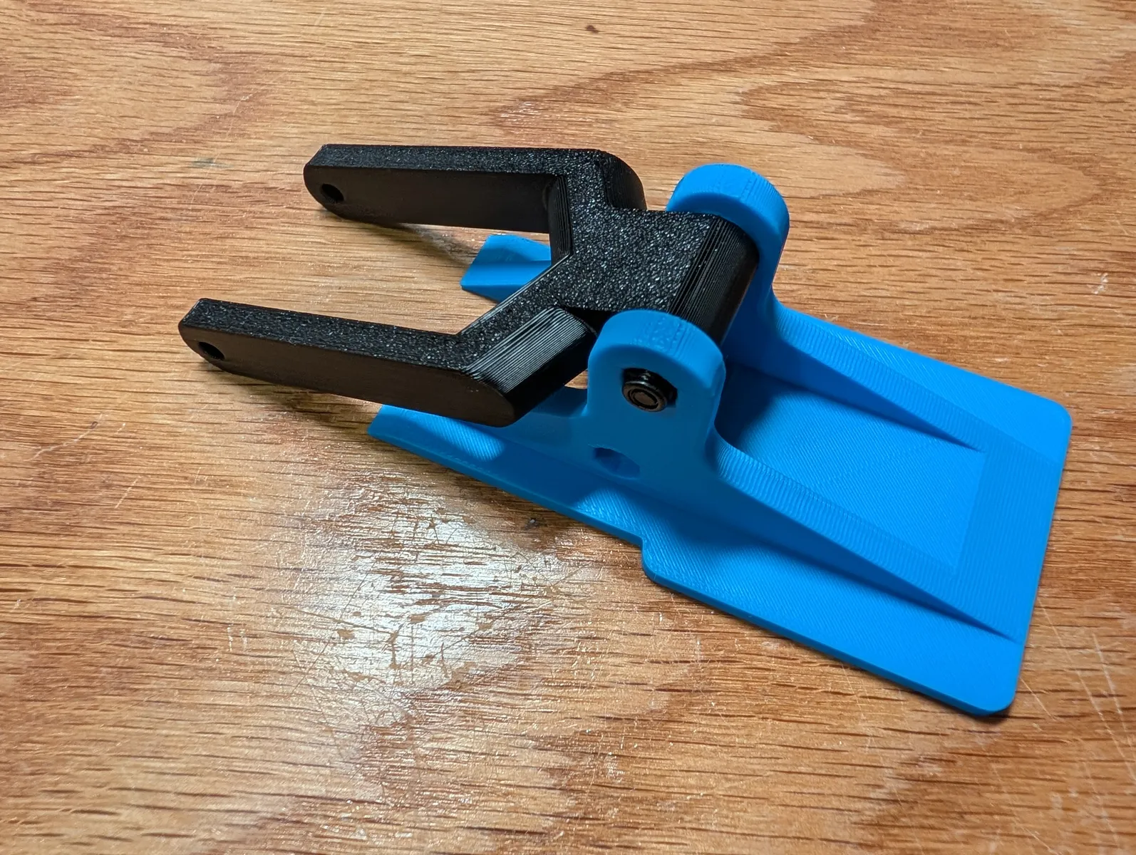
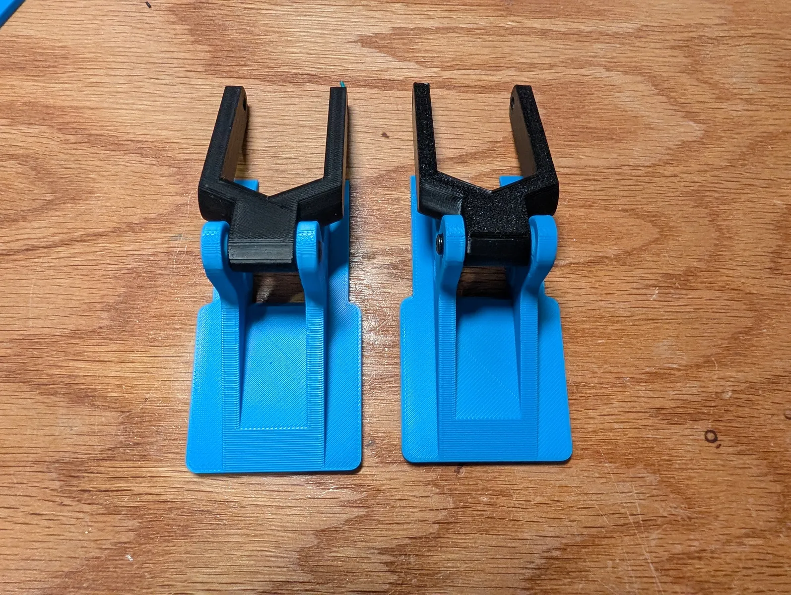
Select either geared lever. Slide in a geared lever into the finger assembly with it's flat face coplanar with the finger's flat flace. Insert an M3x25 bolt through the assembly and a M3 lock nut on the other side.
Tighten and then back off just until the mechanism moves freely. Repeat with the other finger.

Assemble a pressure sensor
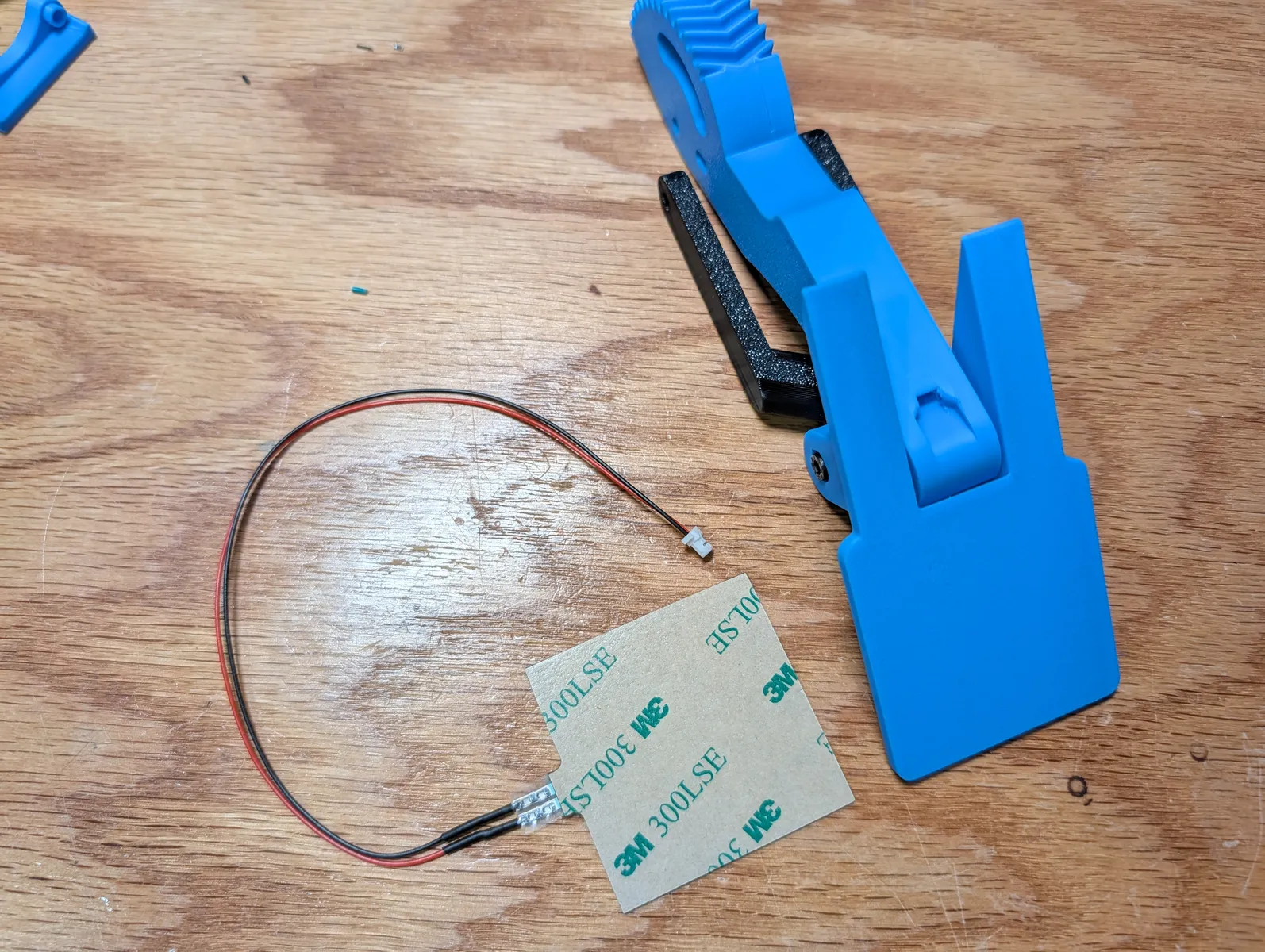
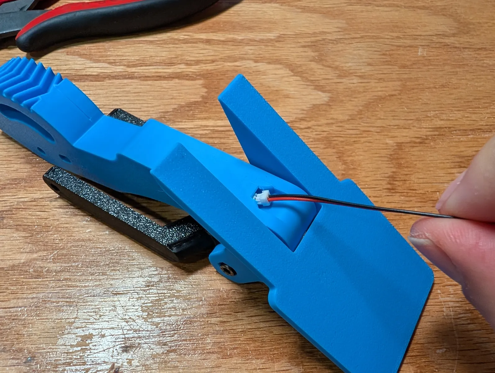
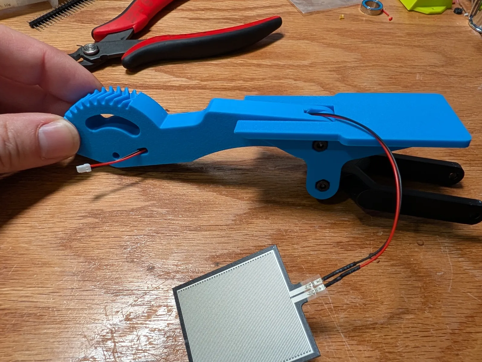
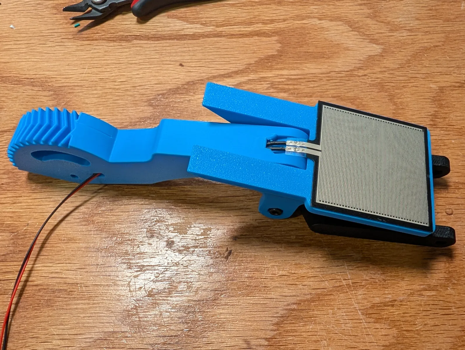
Locate the pressure sense connector. It is a 2-pin 1.00mm pitch male JST-SH connector with 20cm wire ends. Place heat shrink tubing on the wires and solder them to the pressure sensitive resistor. Polarity is irrelevant. Clip the wings off the JST-SH connector with flush cut wire clippers and feed the plug through the channel in the finger.
Select the finger that has a wire channel inside it. Feed the plug of the pressure sensor through the channel and then stick the resistor pad onto the finger.
Apply grip tape on the fingers
prepare at least four strips of 110x37mm fingerboard grip tape.
Lay the finger on the table face up with the finger pad and gear lever's flat faces coplanar, using the linkage as support.
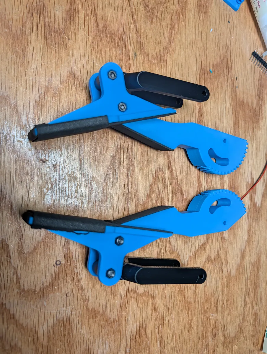
Stick one pad of grip tape on the finger in the longer direction. Start from the top edge of the finger (nearest the gear) make one end of the foam meet this edge, stick down the foam and you will have about 10mm sticking off the end. Fold it over the edge. Press the finger flat against a desk to firmly stick it down everywhere.

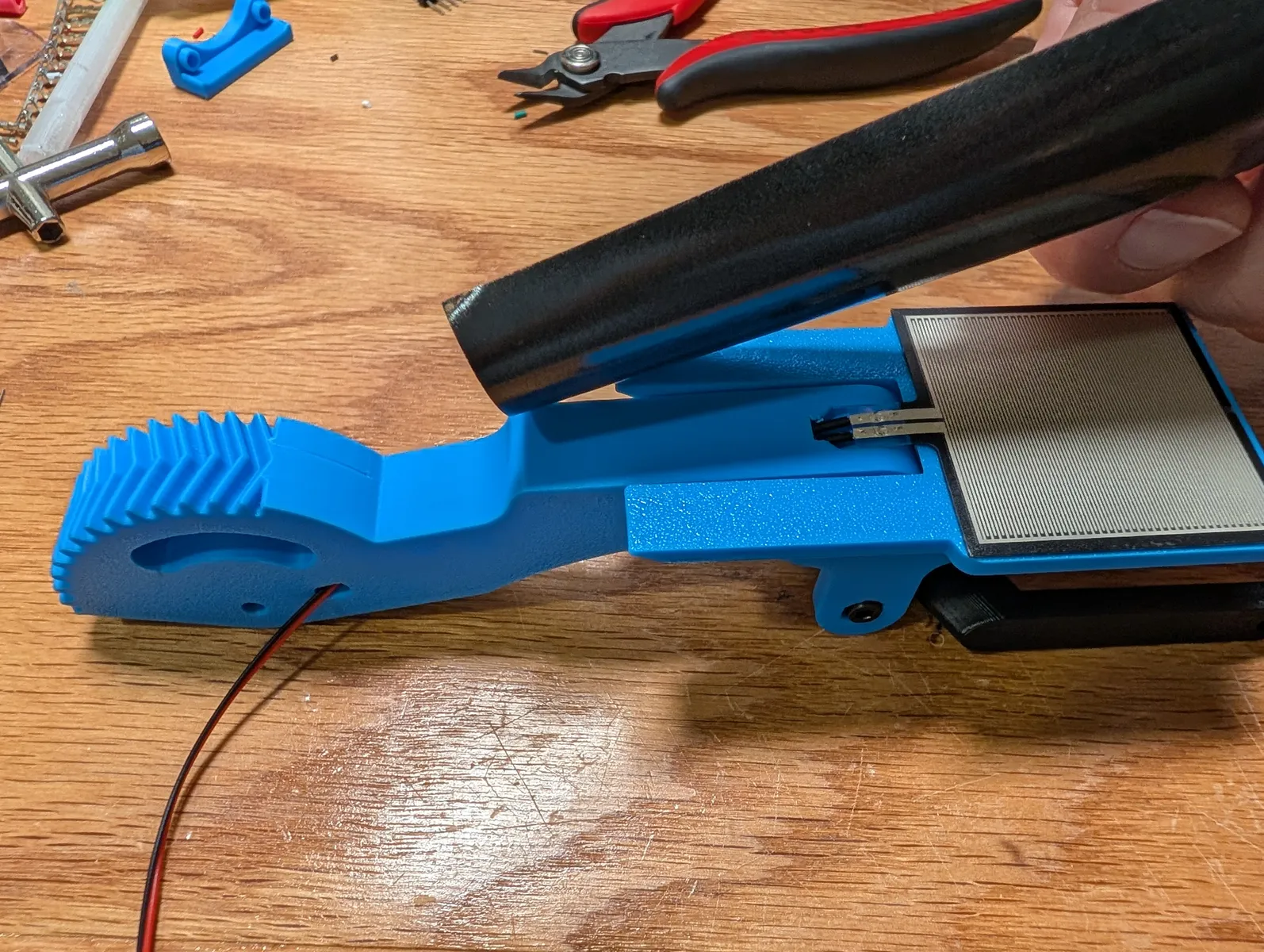
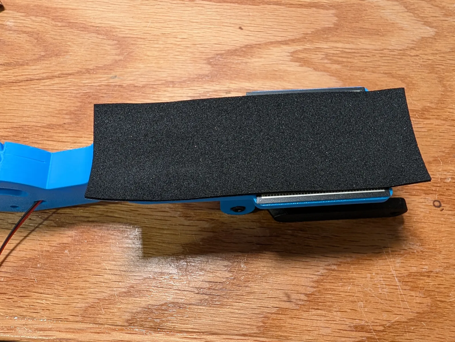

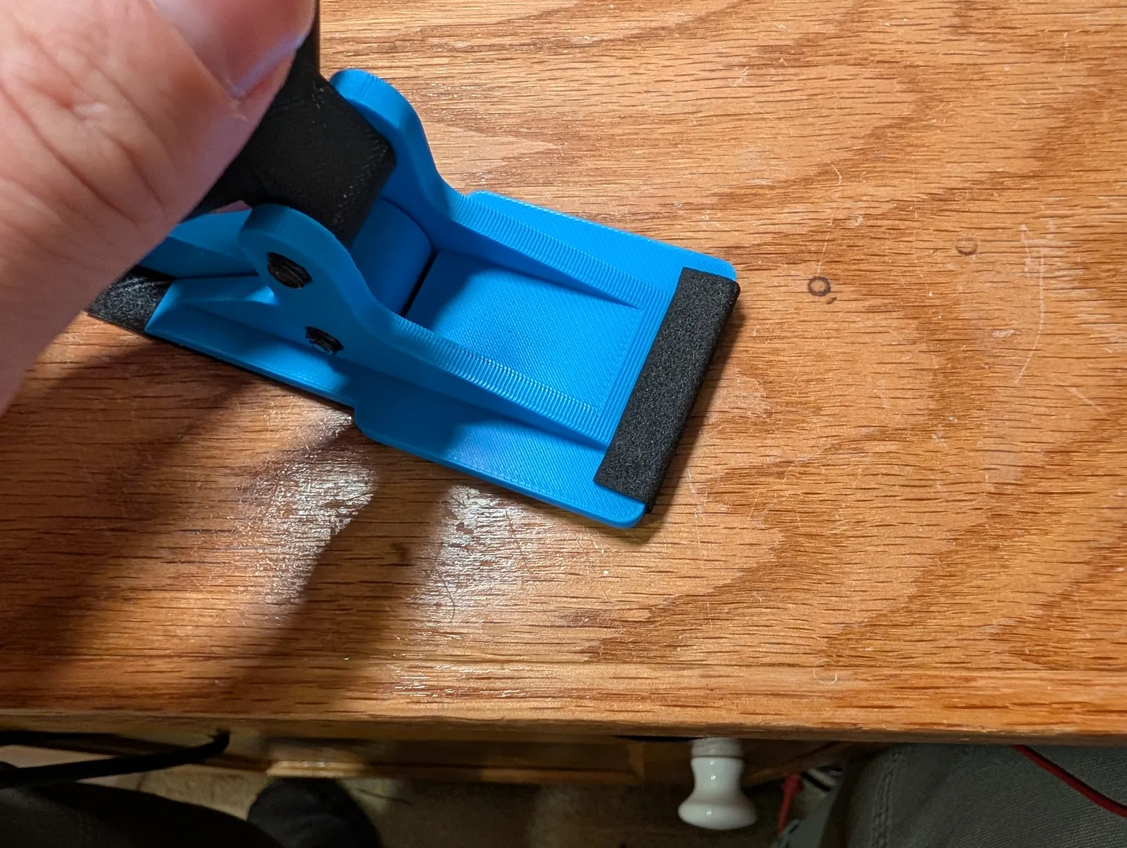
In a perpendicular direction stick another sheet of adhesive foam over the fingertip, folding 10 mm around each side.
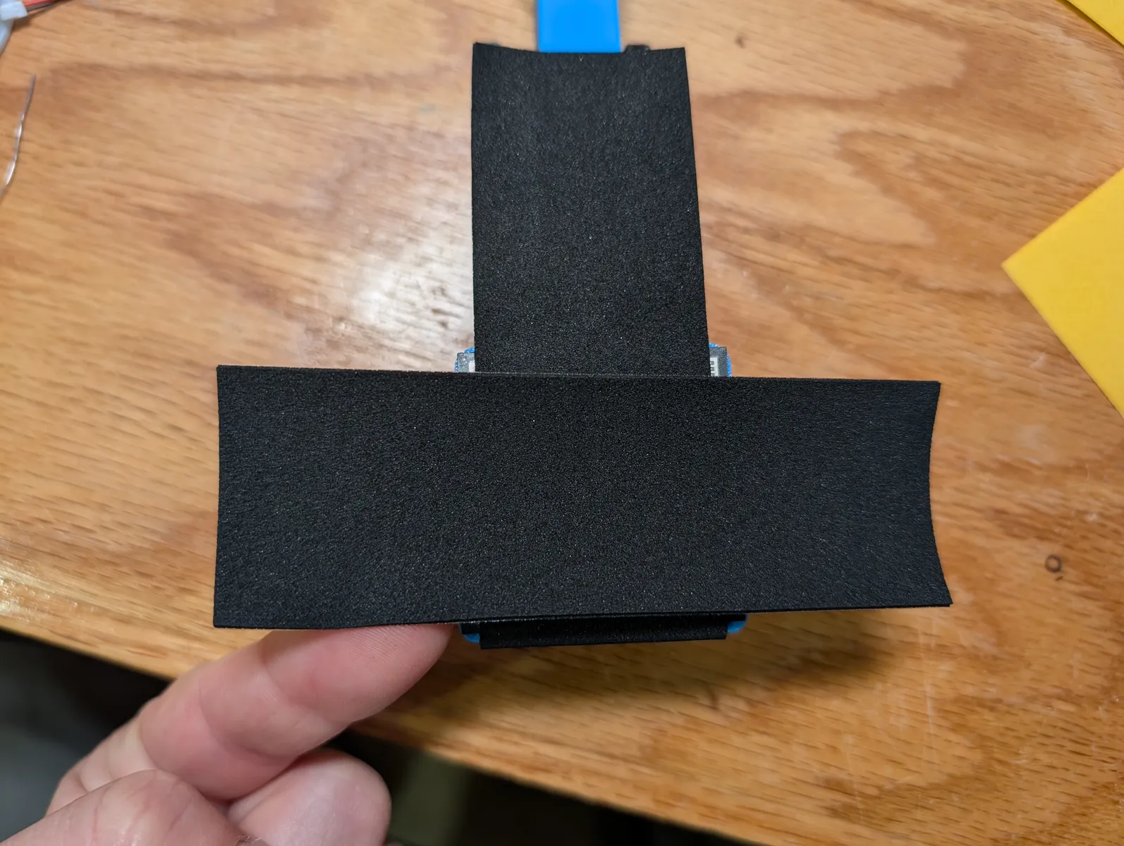

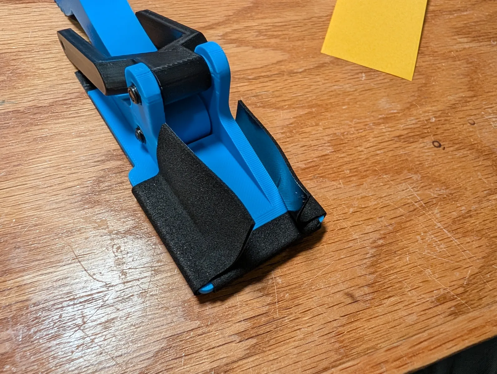
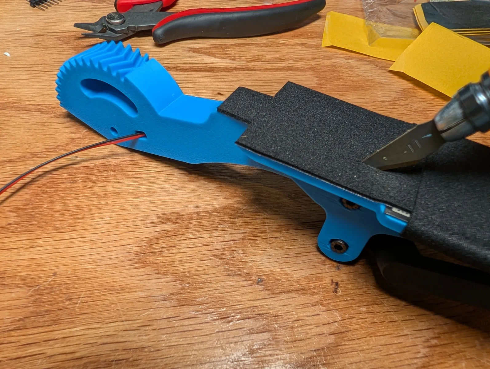
Then with a hobby knife, cut away any excess foam.


Flip the finger face up and cut the foam right down the crack where the two finger peices slide past eachother as pictured, and flex the joint to make sure everything stays stuck in place.
Repeat with the other finger.

Motors
Attach the aluminum servo horns to both motors with the included M3x6 center screw. Use the one with the ridges inside.
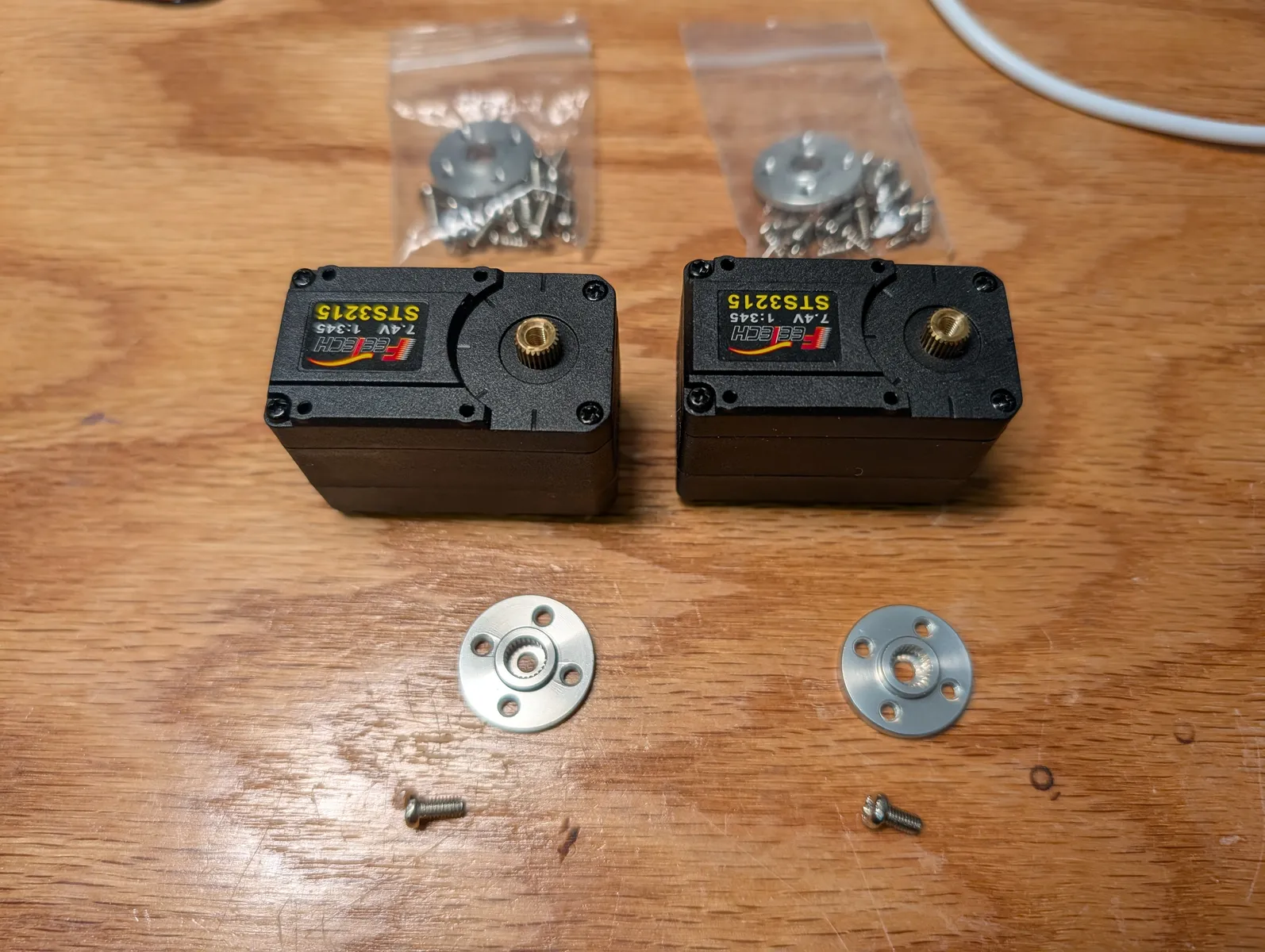

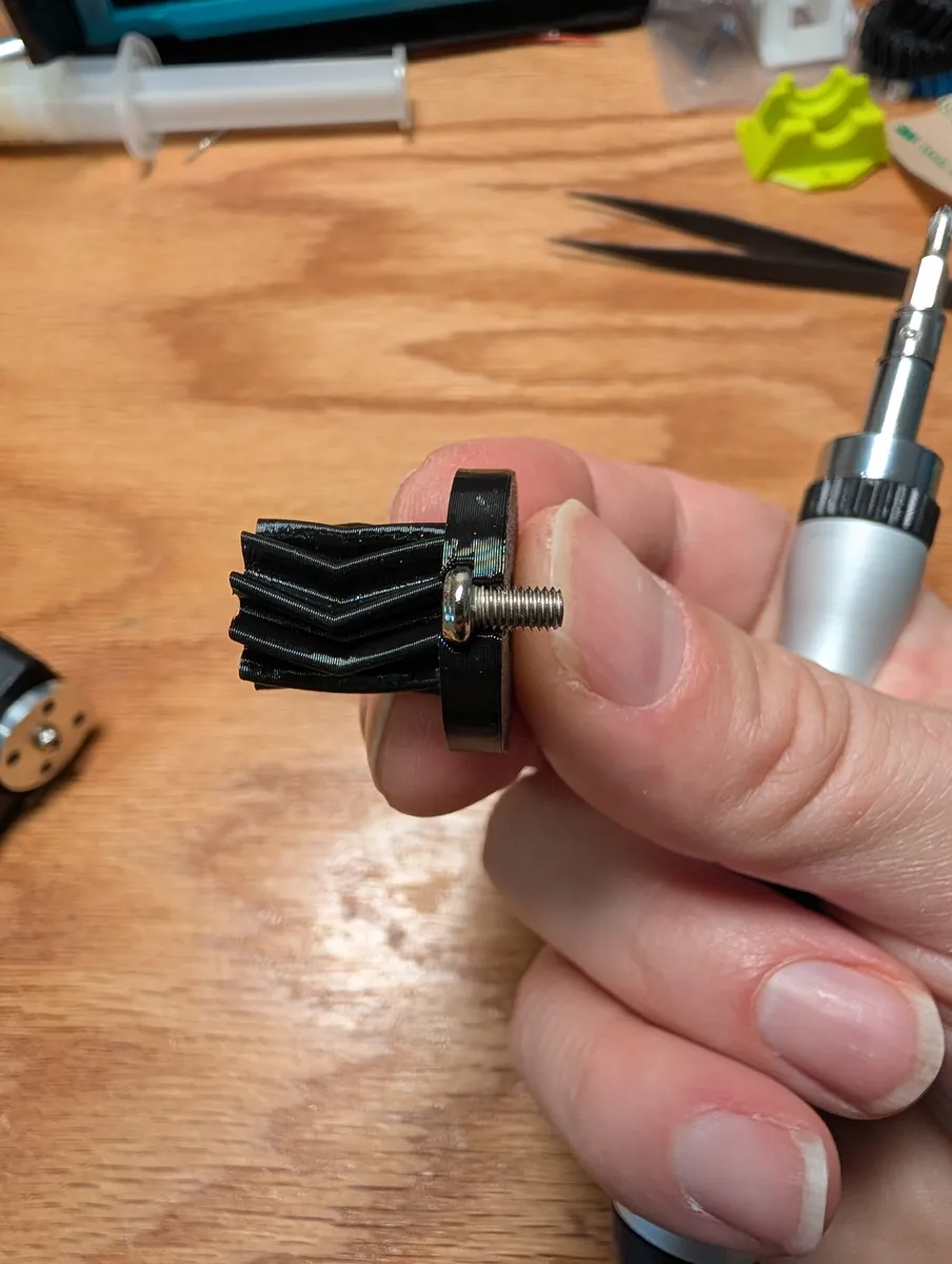
Snap two of the m3x6 screws that come with the motor into the finger drive gear from the sides. Screw the drive gear down tightly to the aluminum servo horn of one of the motors.
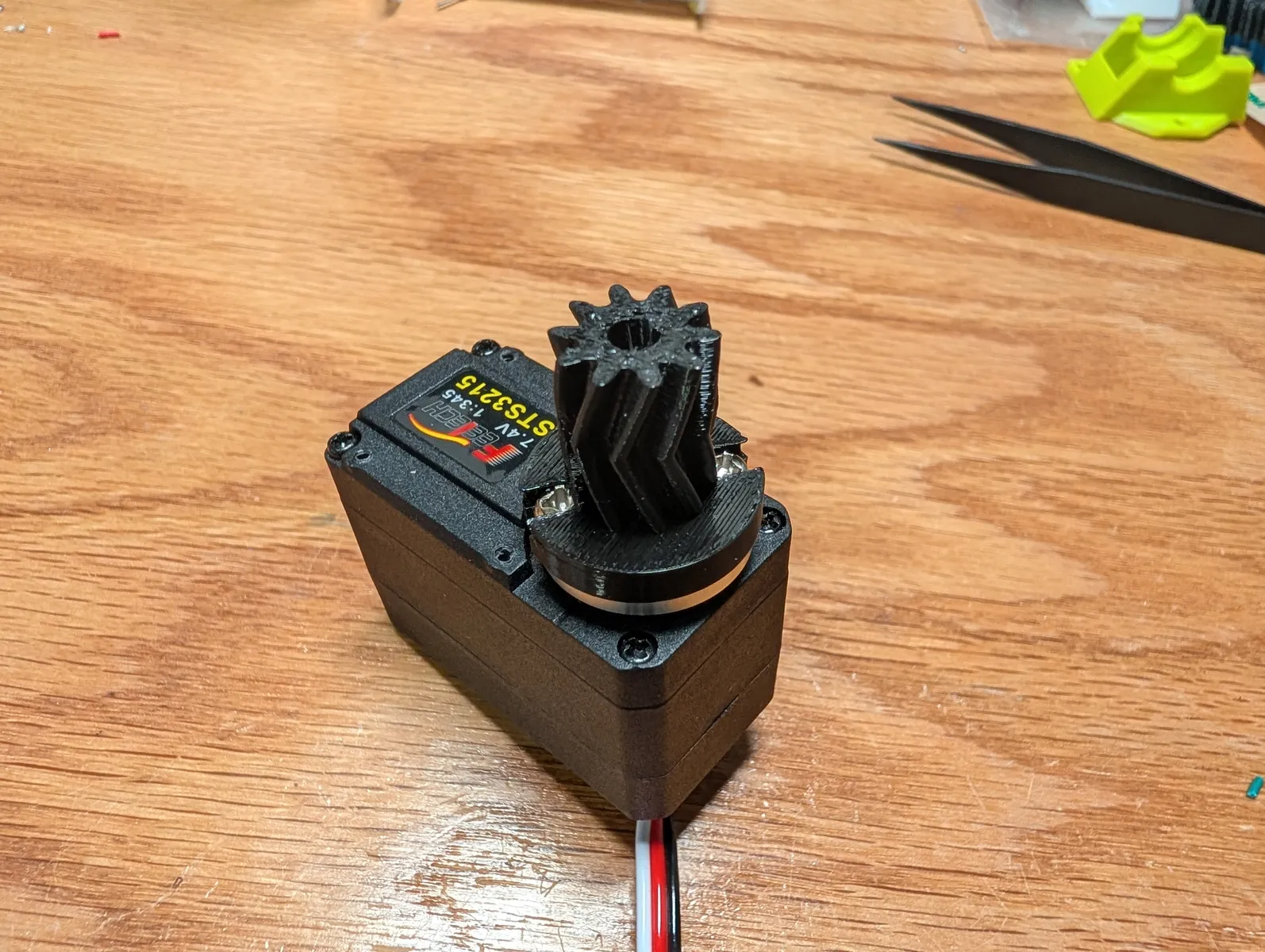
Plug a three wire SPOX cable into each motor. (The wire that comes in the box with the motor)
Body Assembly
After printing, tear the ears off the mechanism lid print. Clean up the area the sacreficial bridge was supporting with a sharp tool.

Attach the finger motor to the outside of mechanism_lid with four of the smallest screws included with the motors.
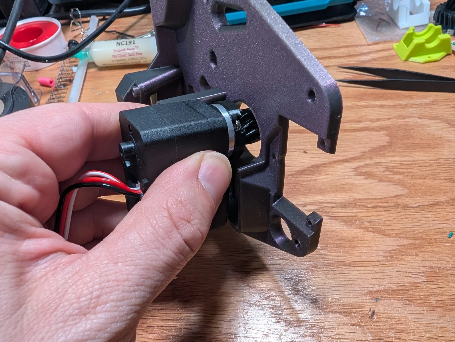
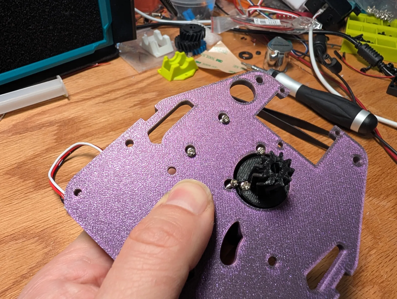
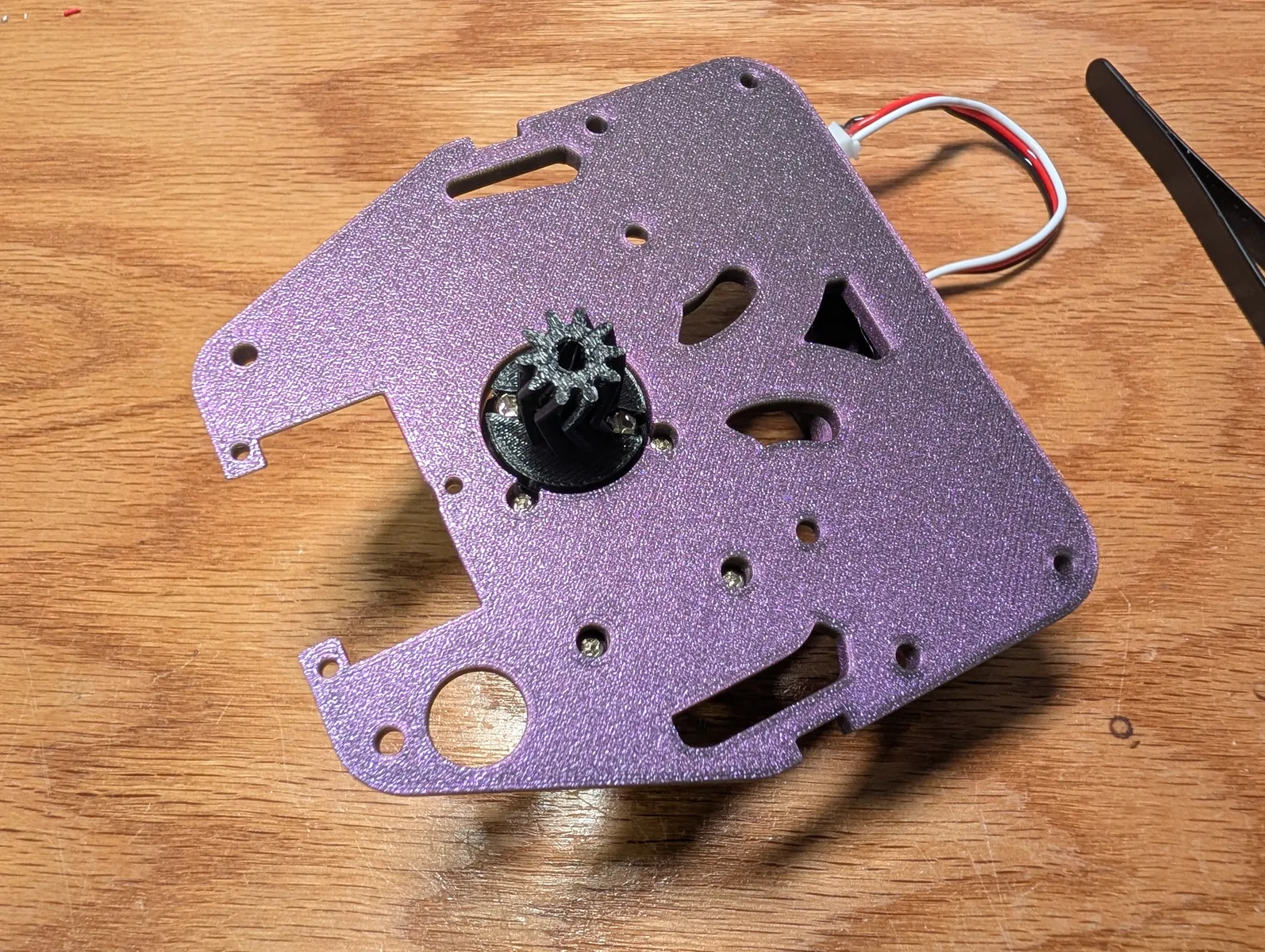
Locate the printed back plate (the largest piece) Insert two M3x25 bolts into the back plate from the bottom, hold them in as you place it on the table. A bean bag can also serve as a good place to put the device while assembling it. Place two M3 washers onto the screws.
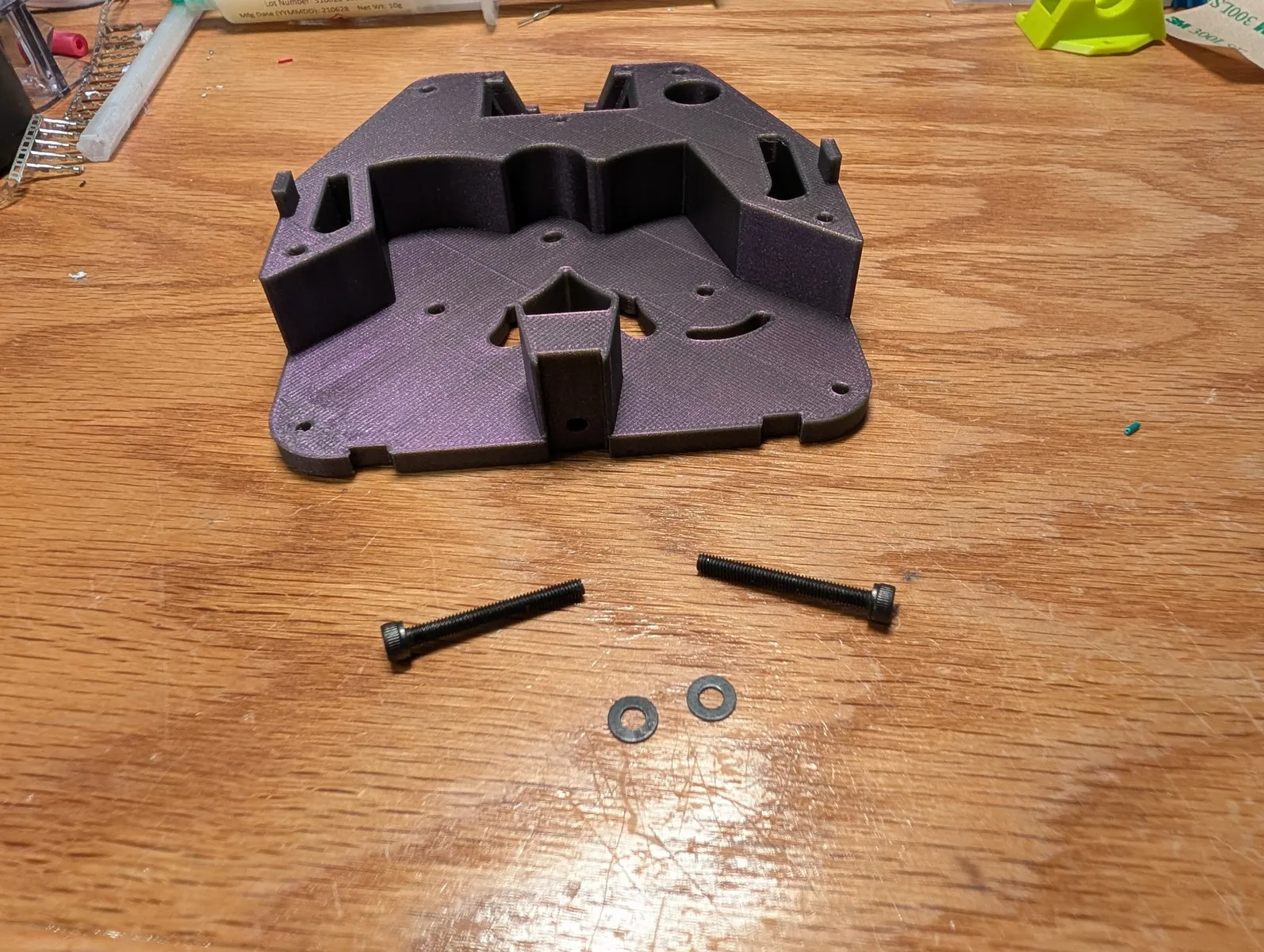
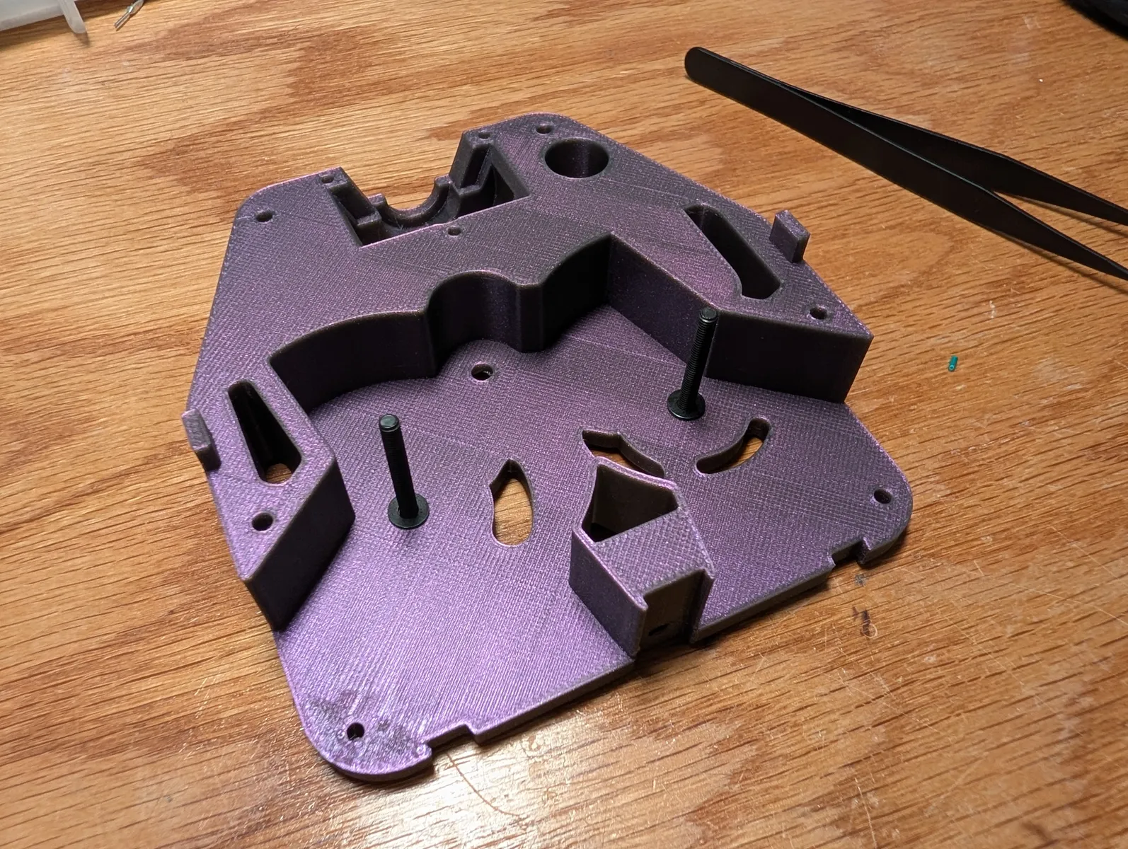
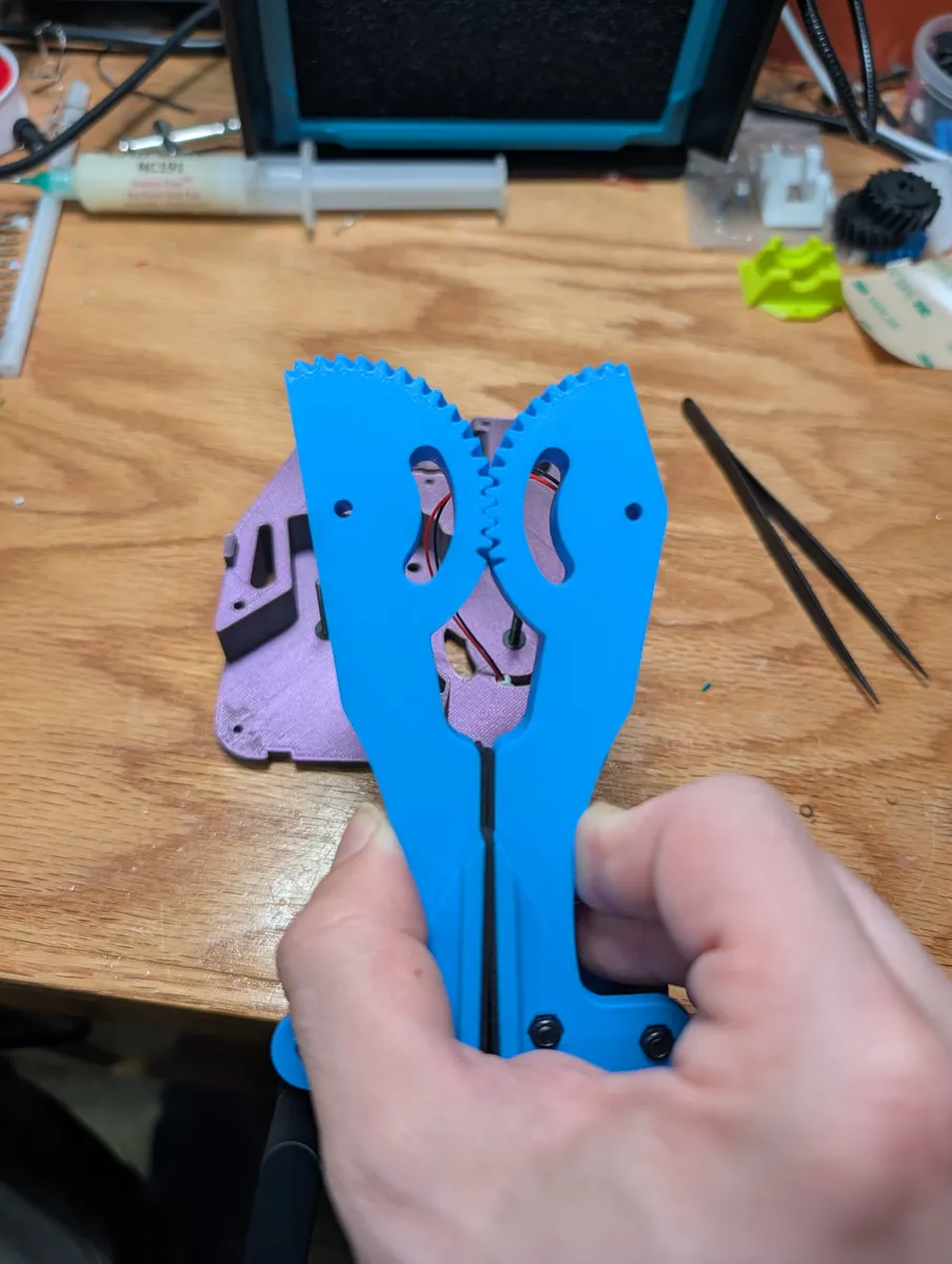
Mesh the two geared levers together in the closed position, making sure they are aligned correctly. They must remain meshed the entire time. Use a rubber band to hold them together if necessary.
Feed the plug of the pressure sense wire through the smile shaped slot in back_plate, and place the fingers on the bolts simultaneously, keeping them meshed, and keeping the sense wire from being pinched anywhere.
Place an M3 washers over each of the two bolts after they protrude from the hole in the geared lever.
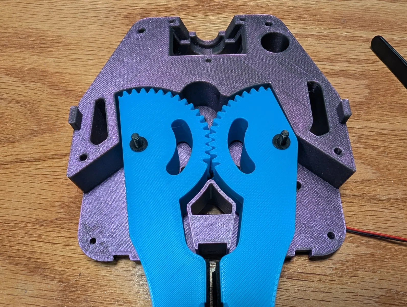
Place the mechanism lid and finger motor assembly onto the back plate, gently wiggle everything in order to get it to fit. The two M3x25 bolts should go through the holes in mechanism_lid and the drive gear should mesh with the finger gears. The alignment tabs on the sides should line up. If you have trouble getting it on there, try pulling the m3x15 bolts back a bit into the fingers, make the gear mesh first, then push the bolts through.
Insert two M3 lock nuts into the hexagonal holes. Tighten the bolts from behind and then back off enough that the geared levers move freely.
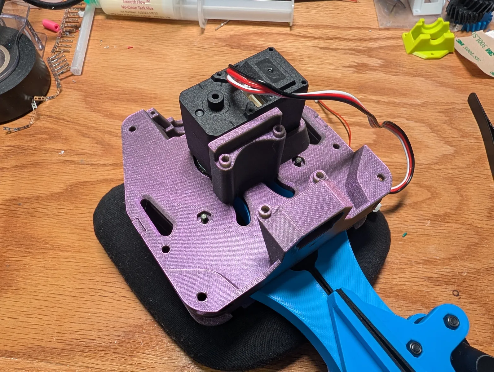
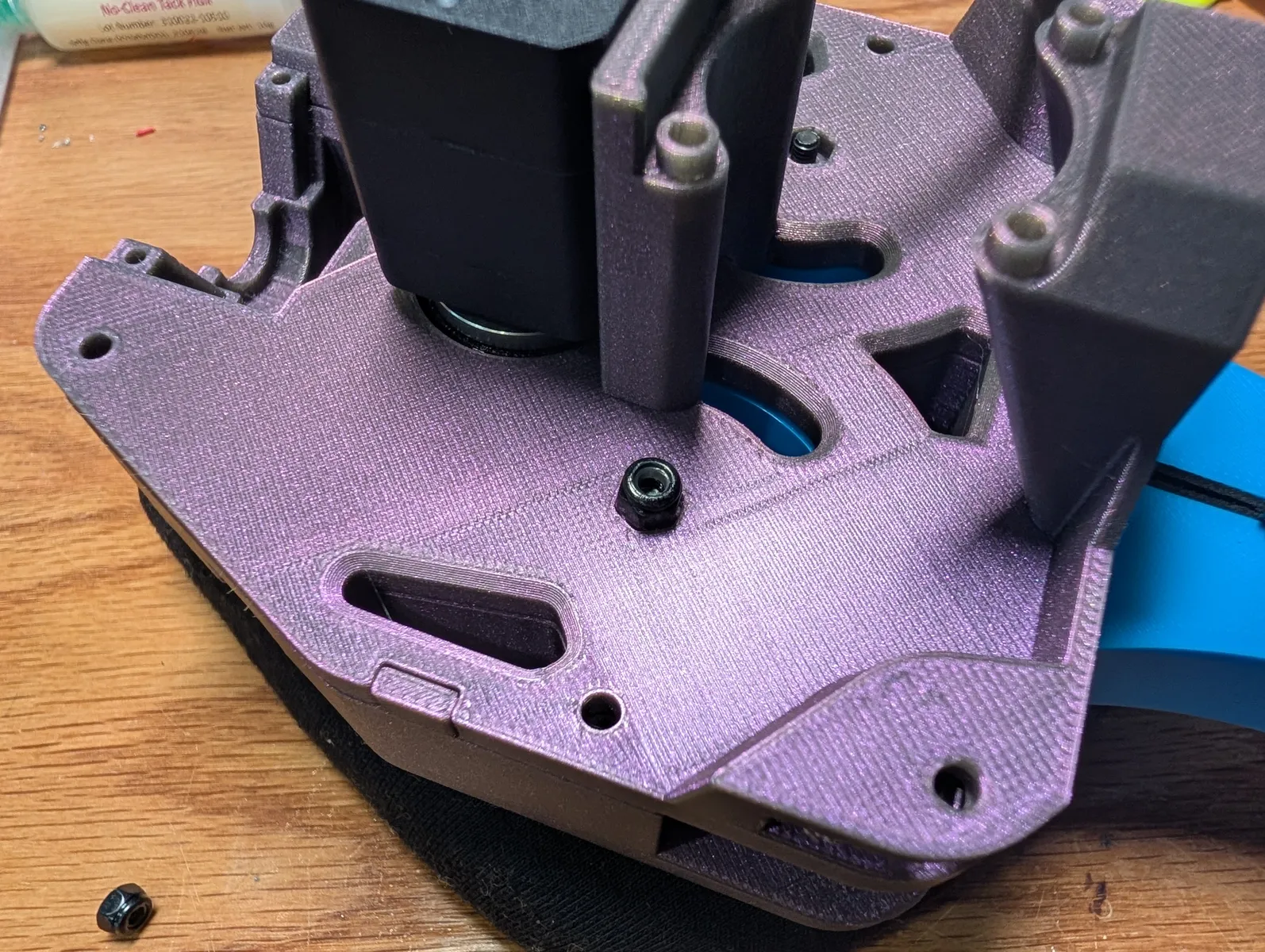
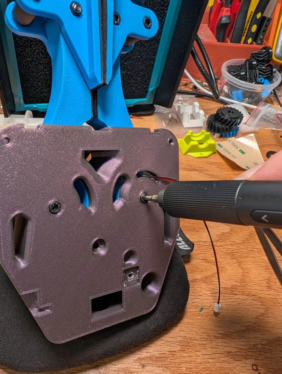
Screw in a single M4x12 screw into the center hole in the back plate. this provides some stability to the finger drive gear.

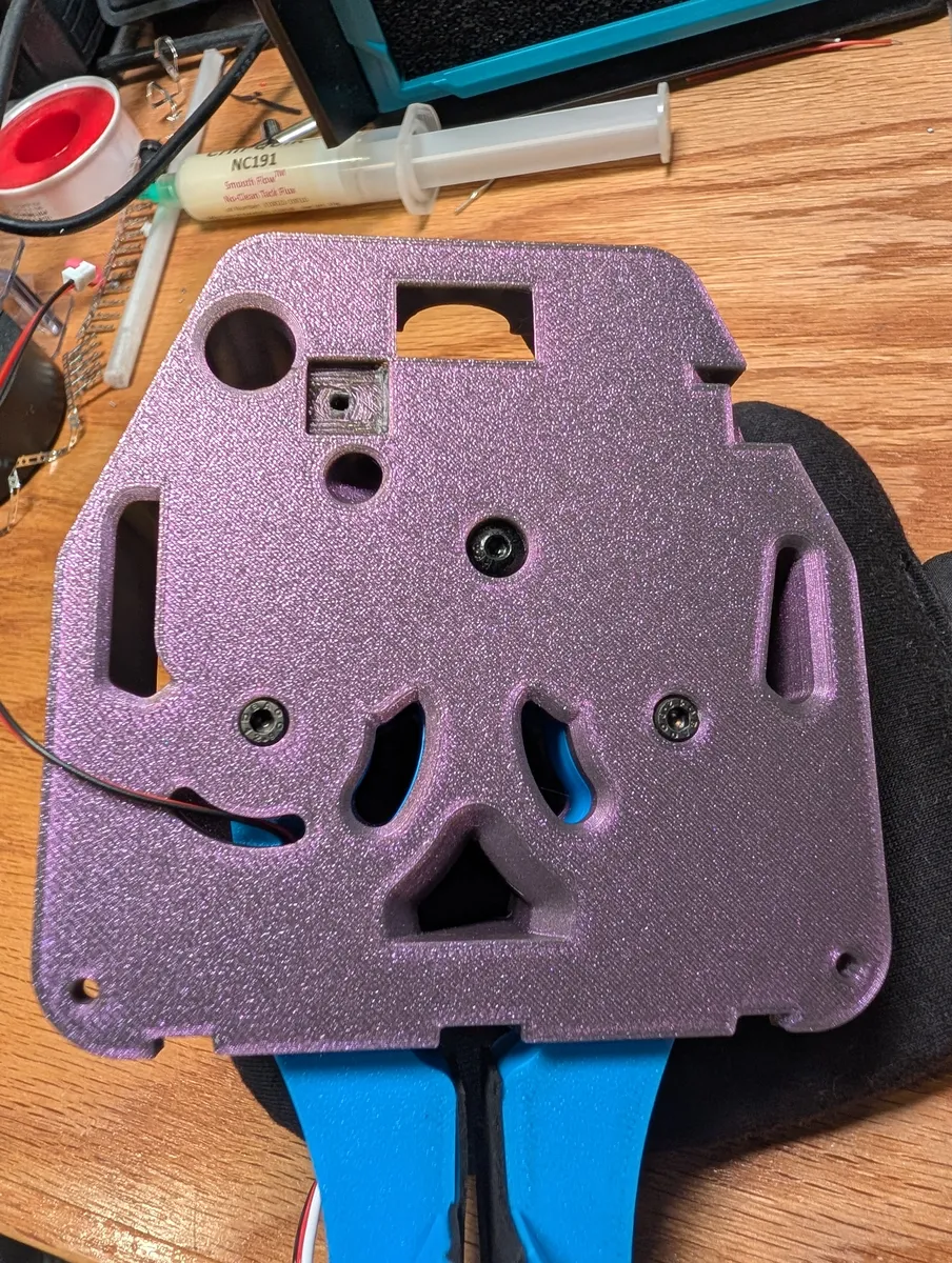
Secure the lid around the edges with four M3x8 screws
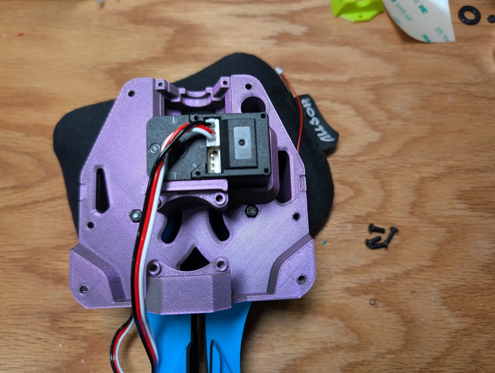
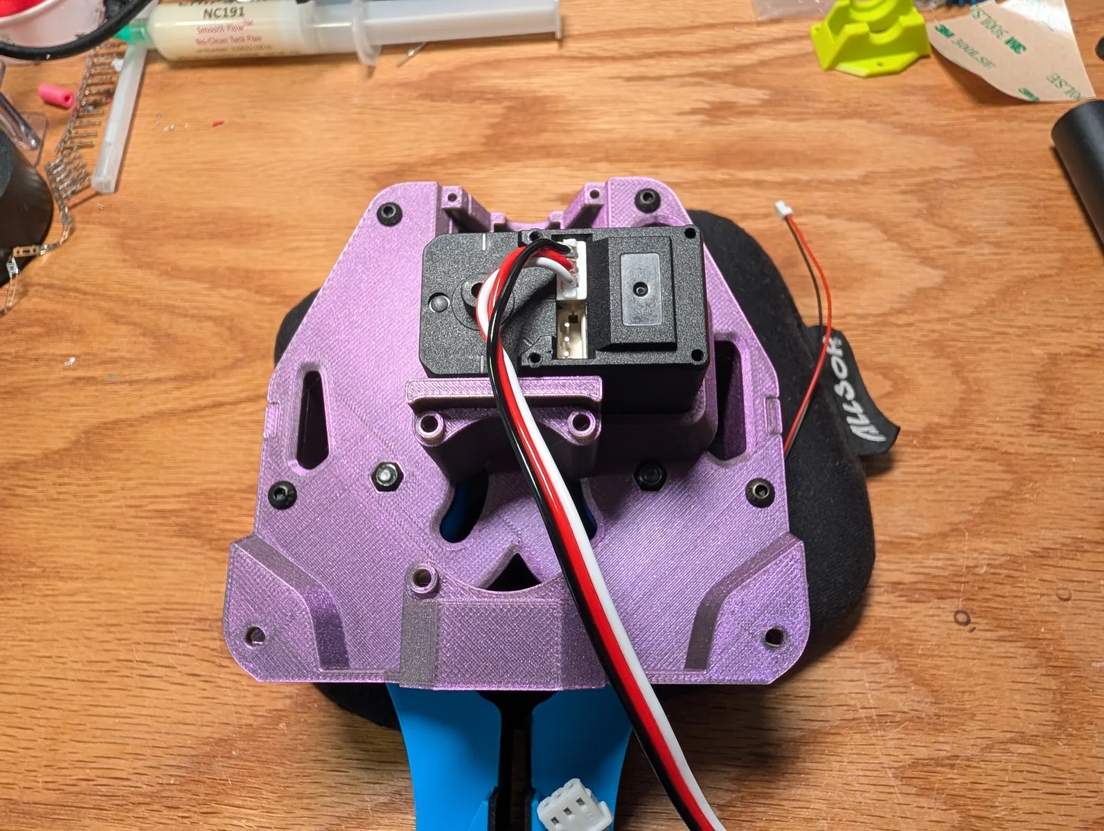
Swing the two fork-shaped linkages up and into their slots. Secure them on the mechanism_lid side with two M3x14 screws. The back side comes later.
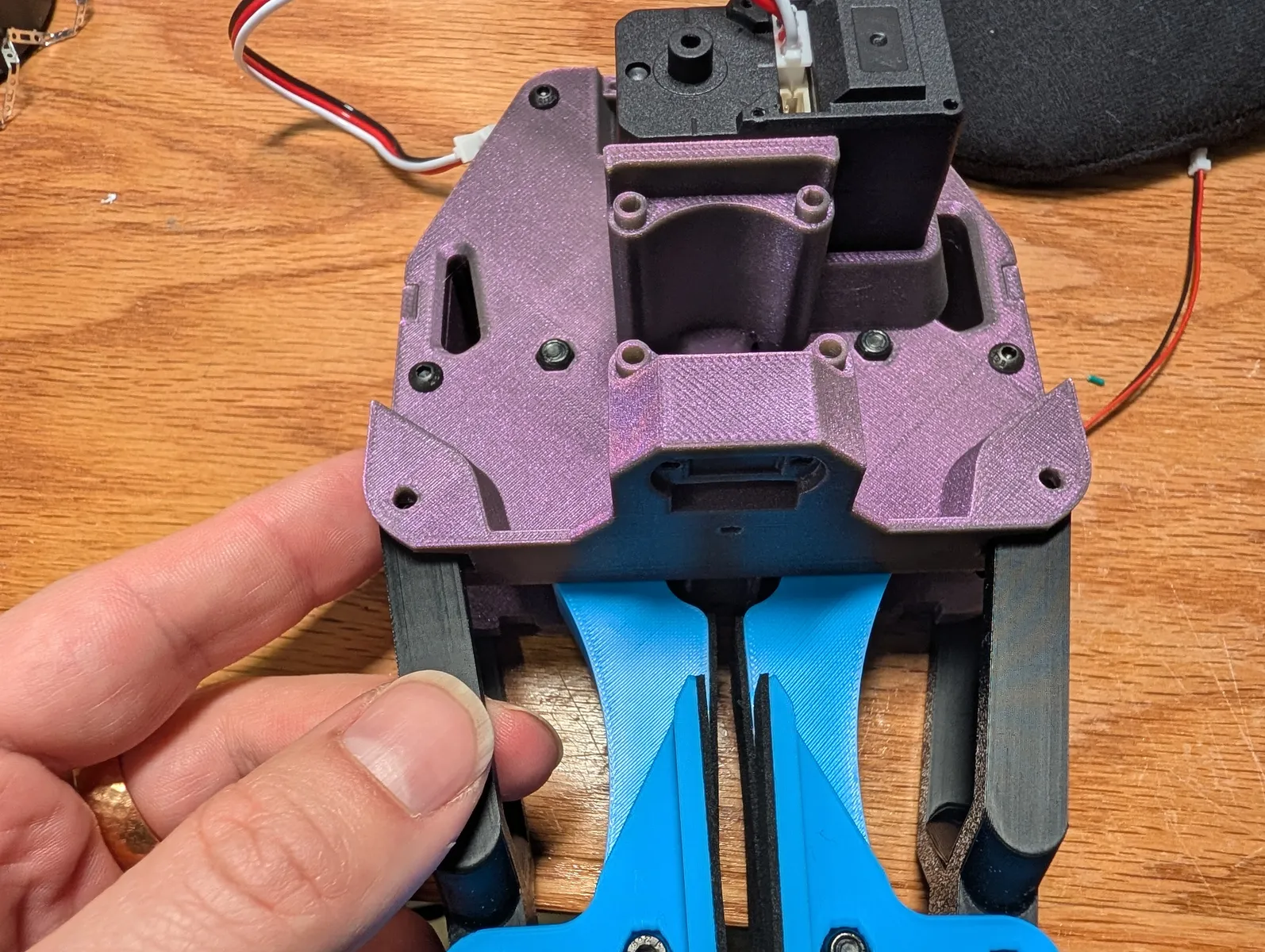
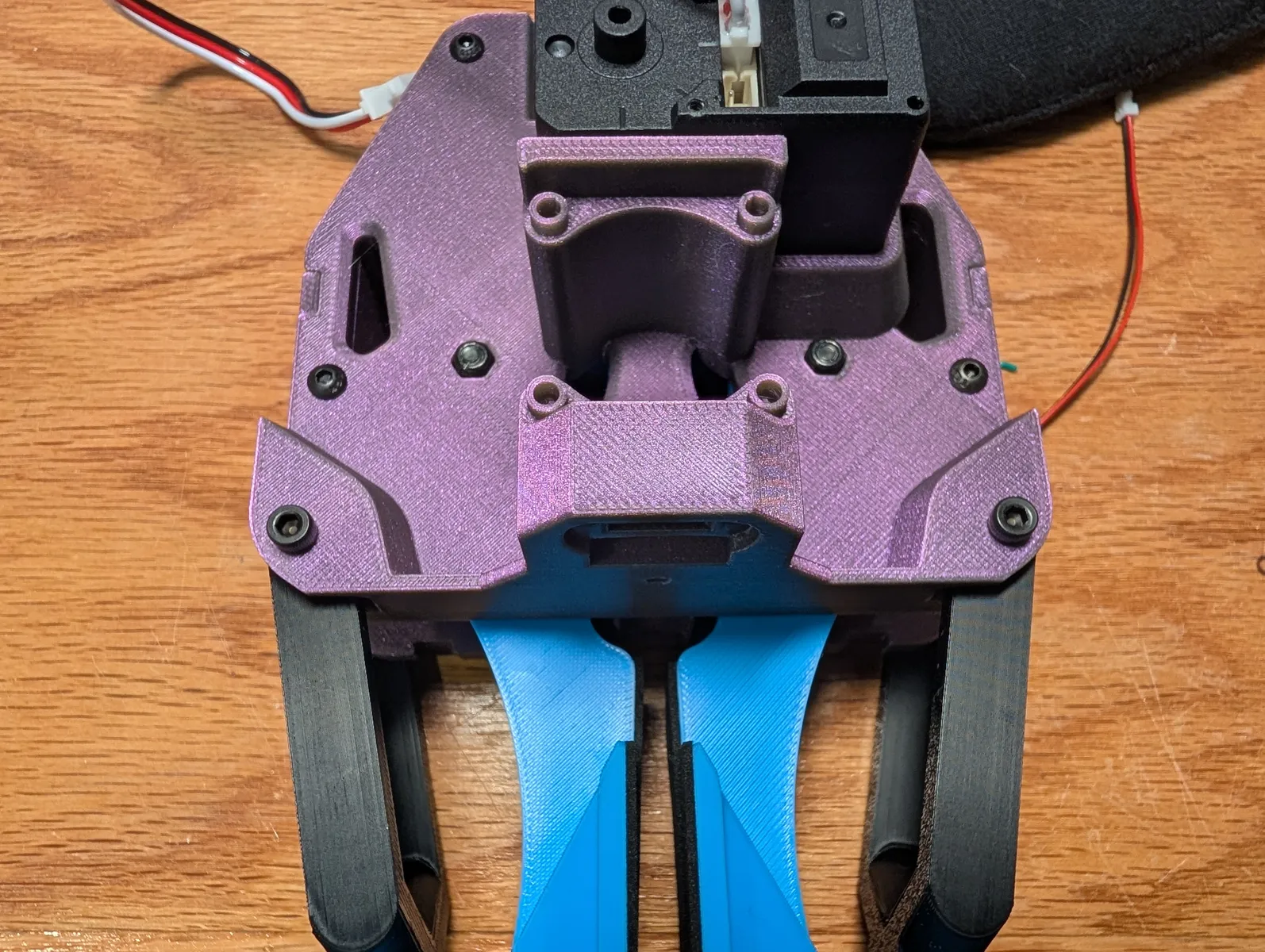
Electronics
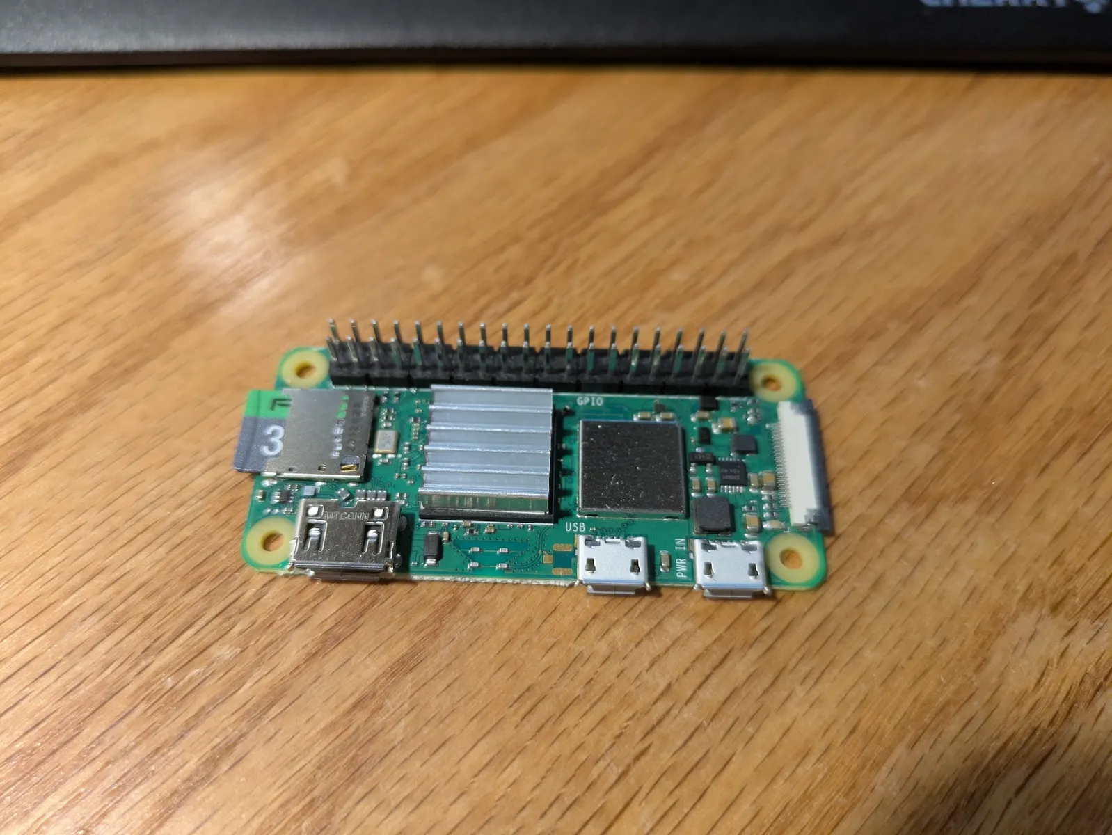
Select a raspberry pi zero 2w. you can either buy the one with the full header, or one with no header and solder header pins on only the first 6 pins of each row. If the pi does not have header pins, solder on a full set. You may find this jig useful if you are soldering the header
Stick a heat sink onto both the black chip (SOC) and the silver one (radio box) Flip the board over and stick two more heat sinks on the bottom under the chips.
Press the Stringman Gripper Hat onto the raspberry pi.
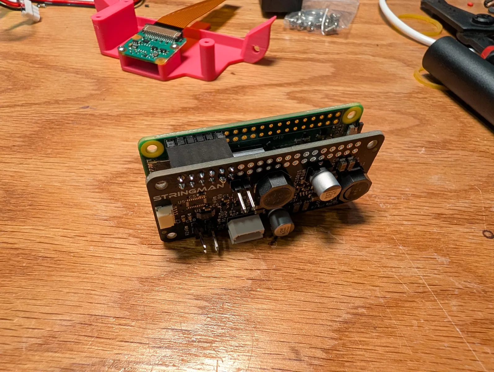
Insert spacers between the two boards, and insert M2.5x16 through the boards and spacers. Only these three corners are used since the ribbon cable is in the path of one of them. use screws and spacers only in the three holes pictured.

Unpack one Wide angle Rasberry Pi Camera Module 3 and install an 8cm mini cable. The wide end of the mini ribbon cable plugs in the camera. Very carefully and gently pull out both sides of the black retaining clip in the Raspberry Pis ribbon cable connector. Insert the ribbon cable, black side up, under the retention clip. Push the clip back in to secure it. If the clip falls out, you can put it back in with tweezers by inserting one side at a time.
Layout the parts as pictured screw the camera to the camera mount with two M2x4 bolts in opposite corners. Then, folding the ribbon as pictured, place the board stack on the mount and screw it in in the three corners that have screws.

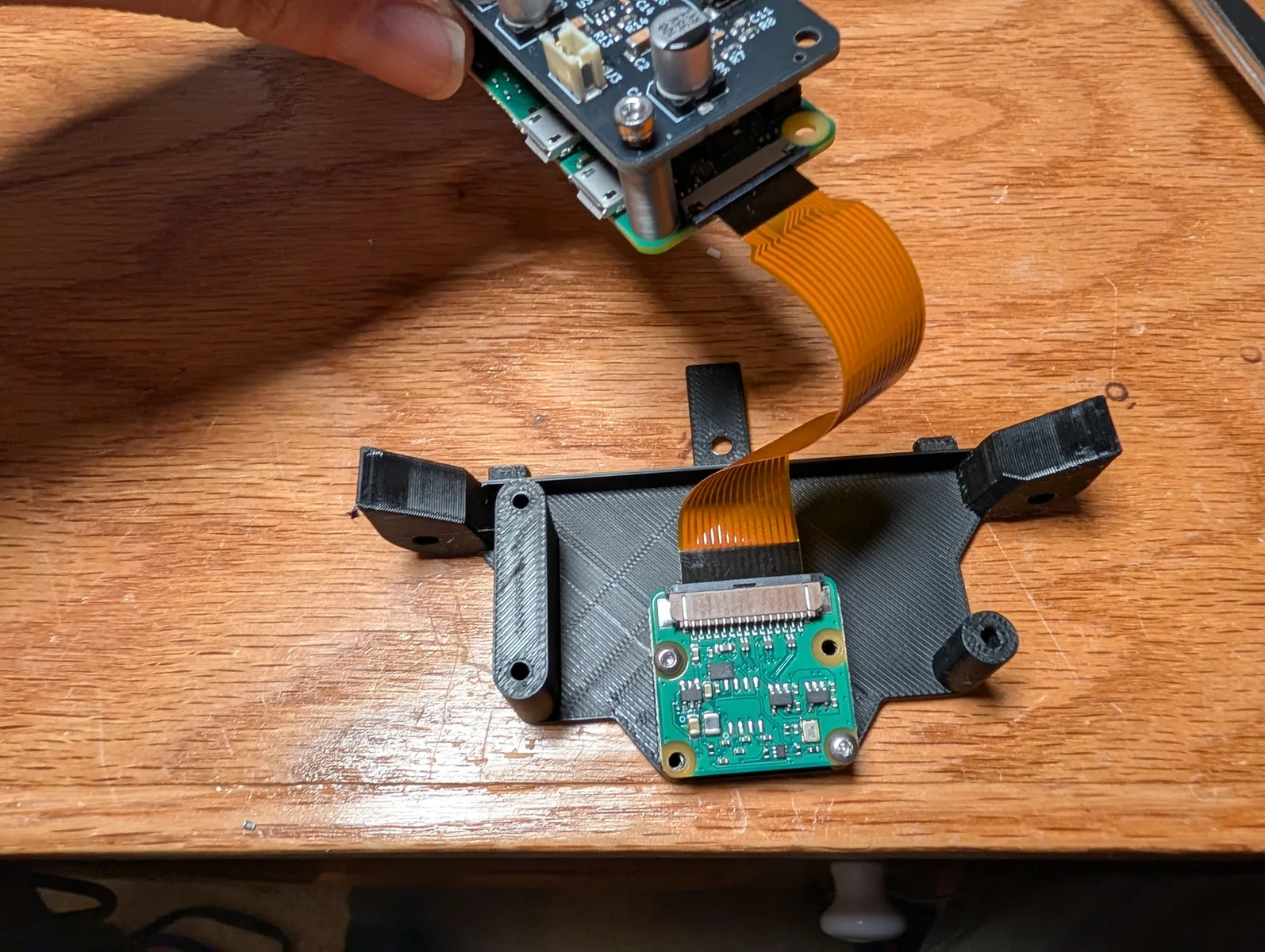
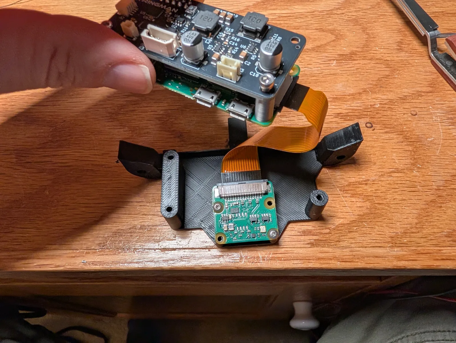

Open the gripper fingers. Attach the camera mount assembly to the back plate with an M3x6 countersunk screw.


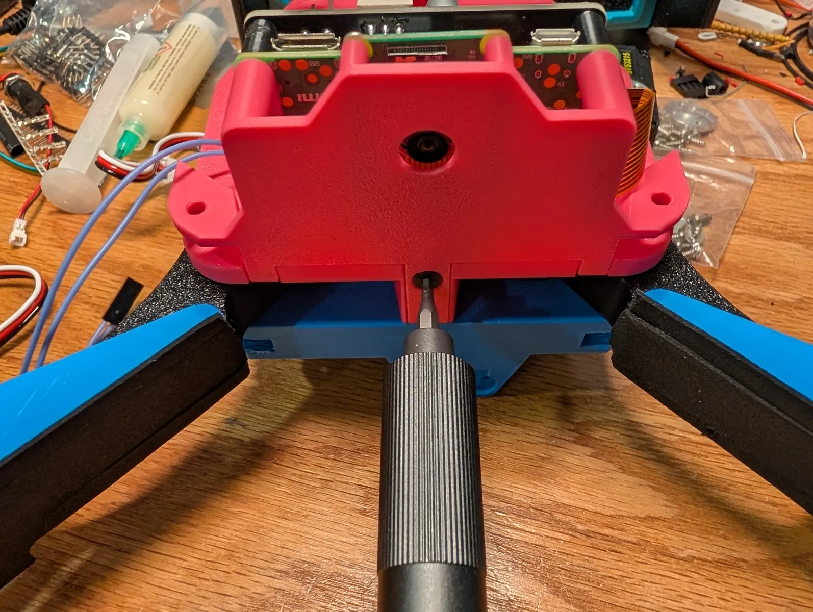
Screw two M3x14 screws into the holes that both hold on the electronics mount and secure the forks from the side that was left unfastened earlier.
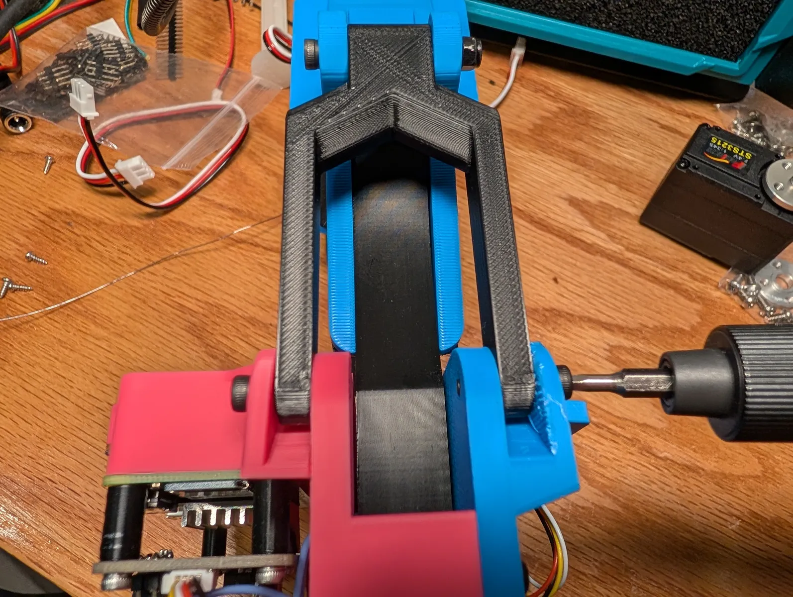
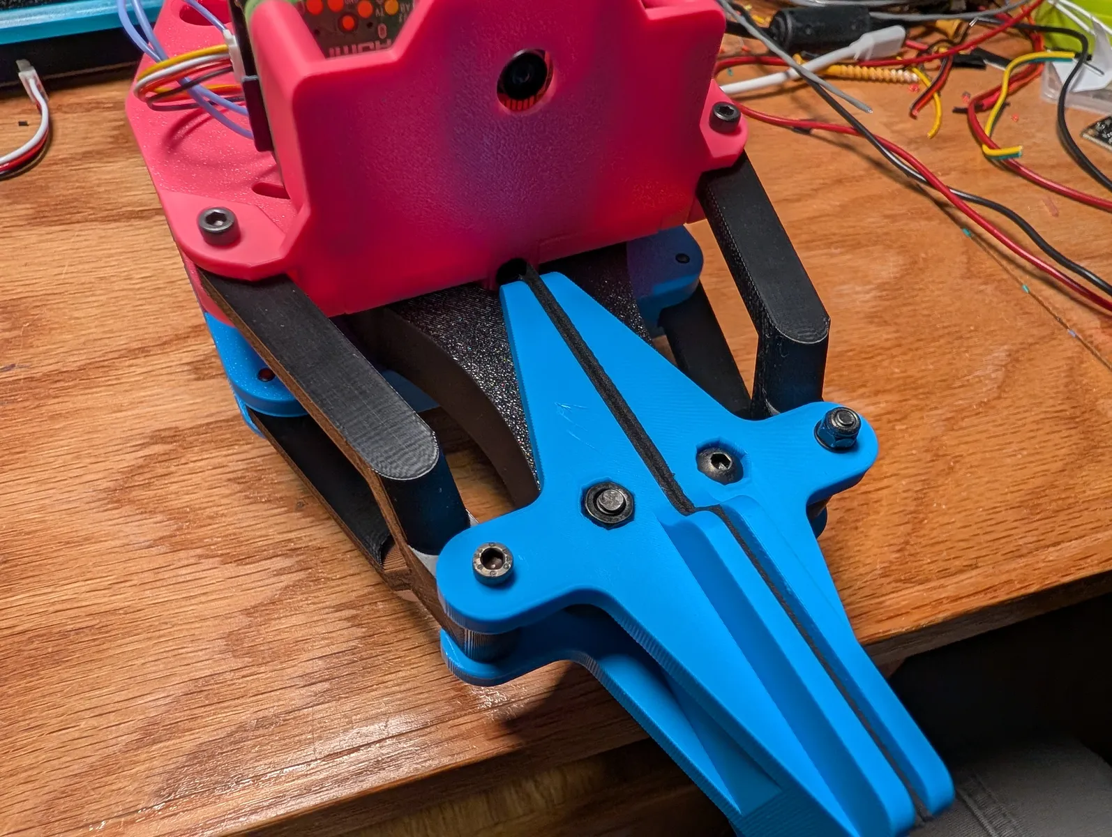
Plug the pressure sense plug into the Gripper Hat's "pressure" socket.
Image an SD card according to the instructions in Raspi Setup and insert it into the SD card slot.
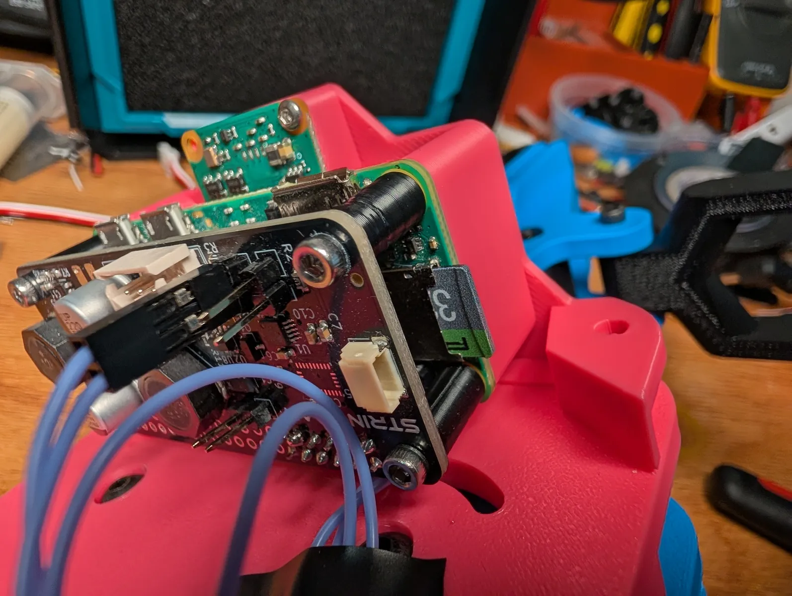
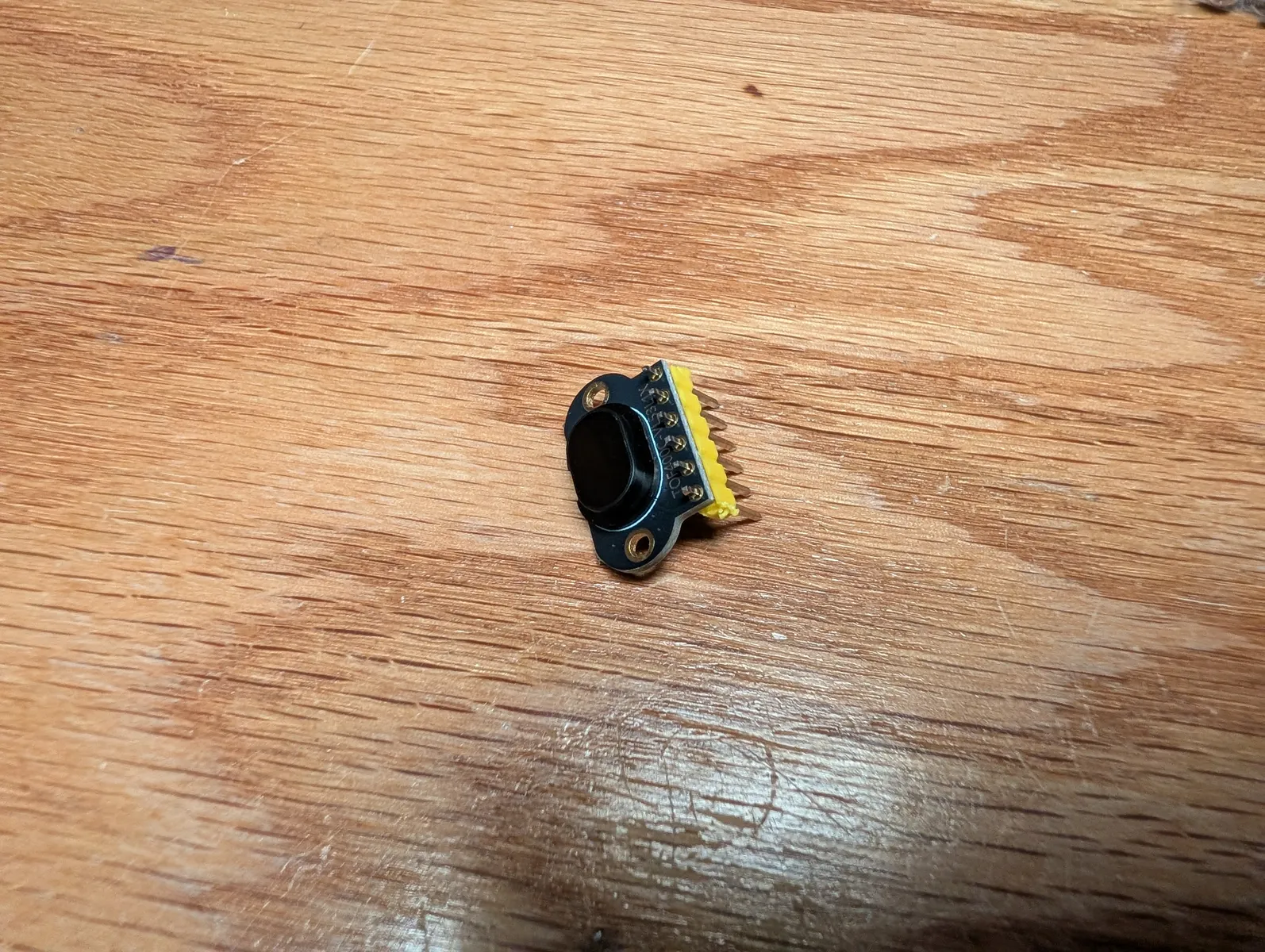
Locate the laser rangefinder and the four wire cable pictured below
If you sourced it yourself, you may need to solder the header
Solder the straight header onto the laser rangefinder. You can solder all six or just the four lablelld VIN, GND, SCL, and SCA.
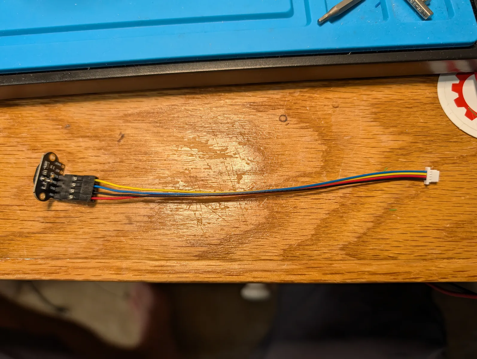
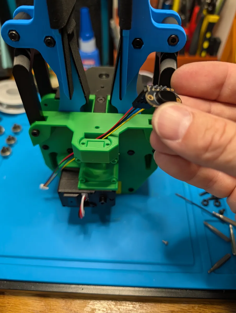
Plug the 4p rectangular dupont plug into the rangefinder. Red should be on the outer edge as pictured below. Feed the wire into the hole below the fan, and out the left side, and then through a hole on the side of the device to reach the front. Plug the JST-SH connector into the gripper hat board.
Screw the rangefinder into it's seat with two M2x4 screws.

Wrist motor
Attach a bracket to the remaining motor in the pictured orientation. Secure with four of the included small tapping screws from the motor box.
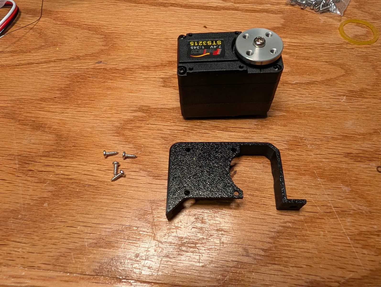
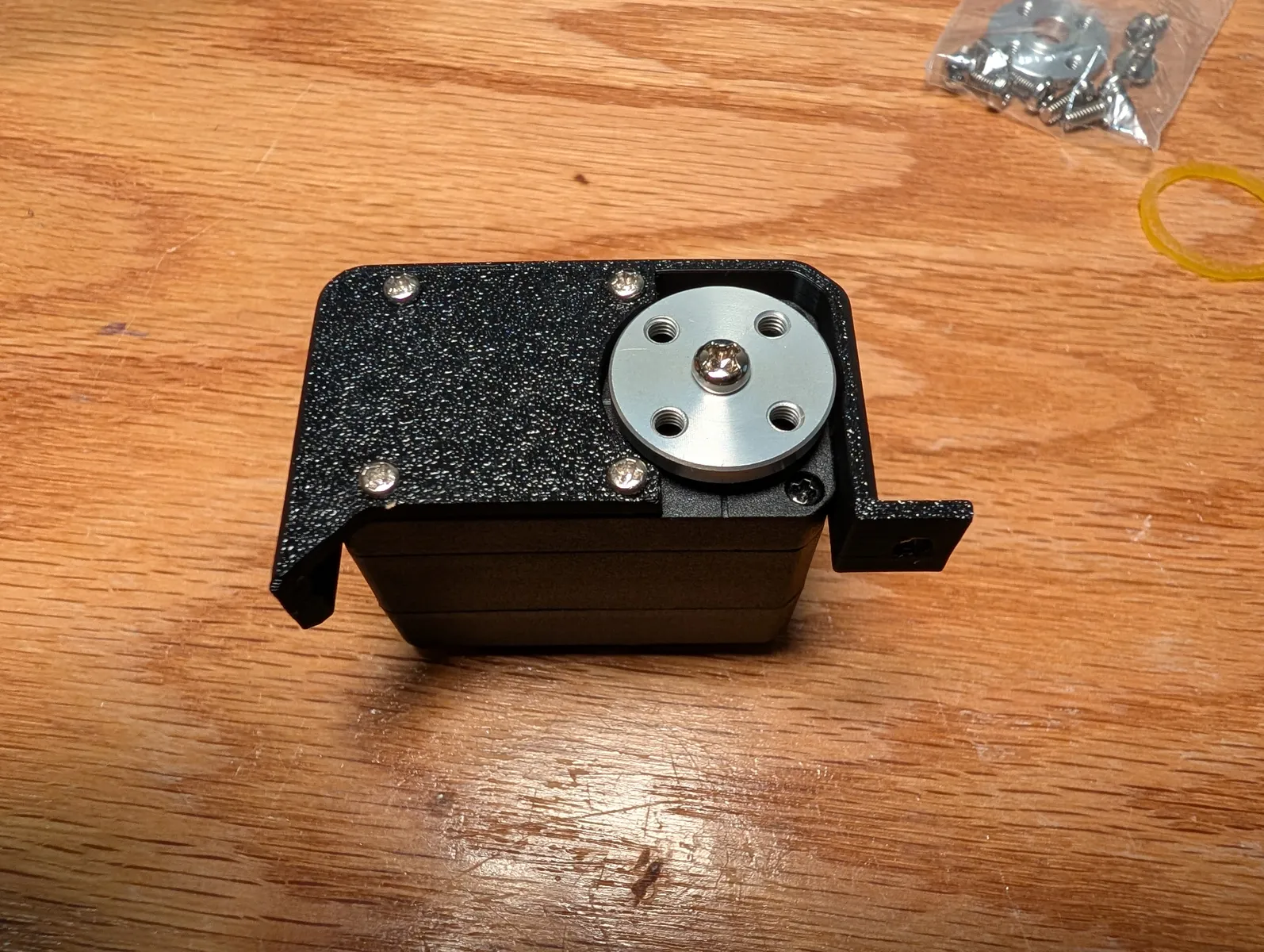
Attach the three-holed helical wrist drive gear to the motor horn with two of the M3x6 screws that come with the servo motor.


Attach this motor bracket to the gripper with two M3x8 screws.

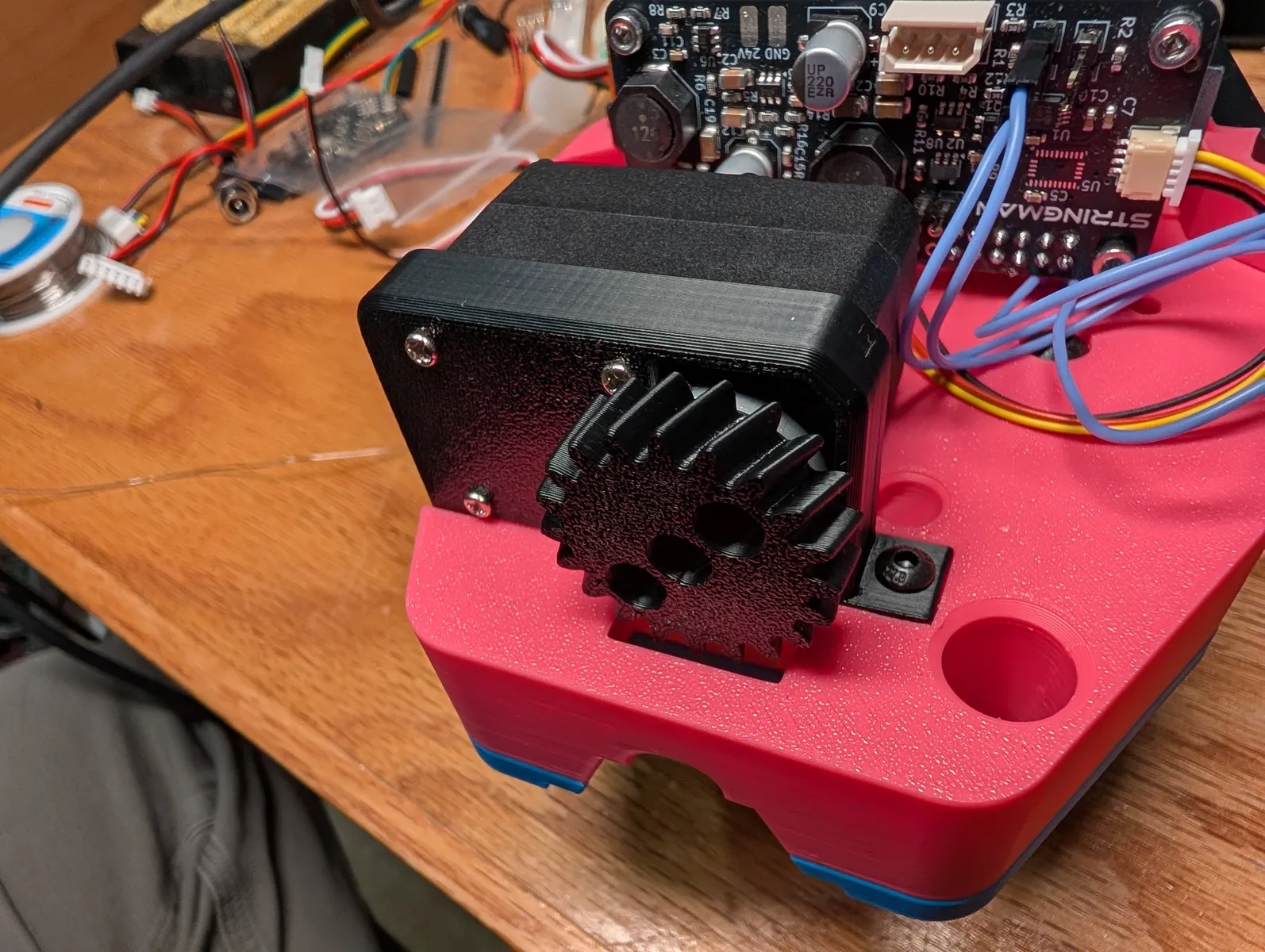
Plug the finger motor into the motor port on he Gripper Hat. Leave the wrist motor unconnected for now.
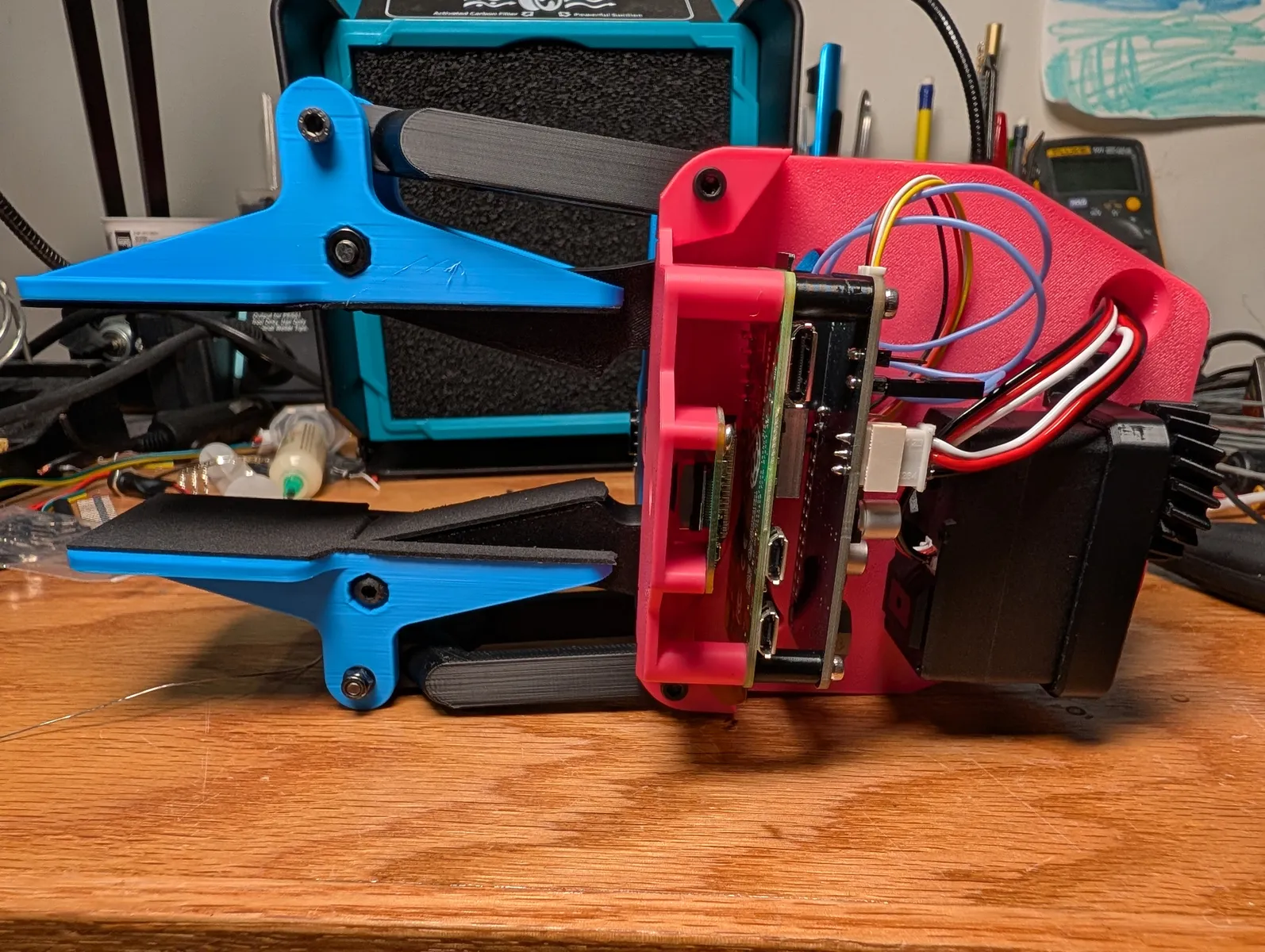
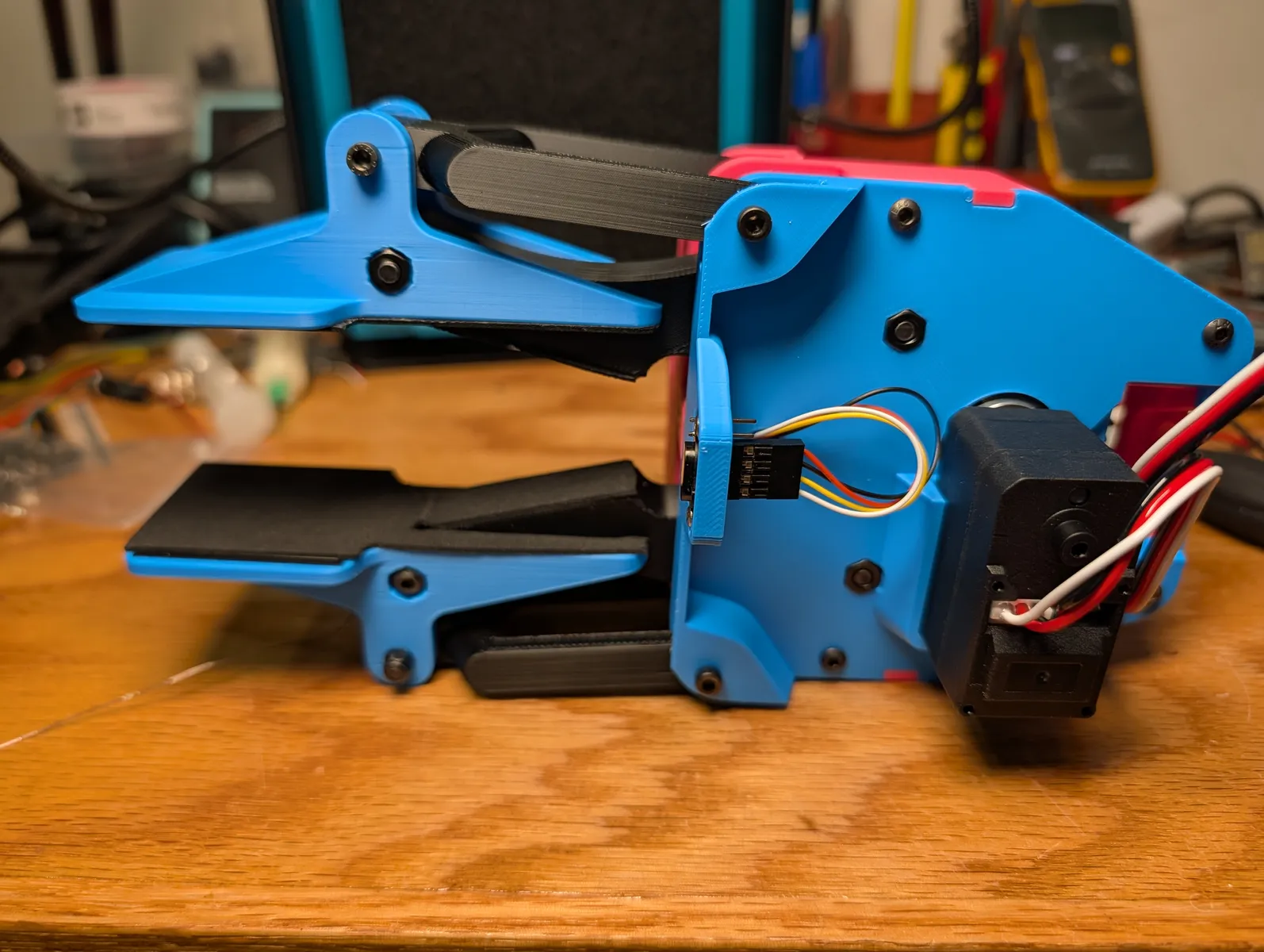
Fan and Power
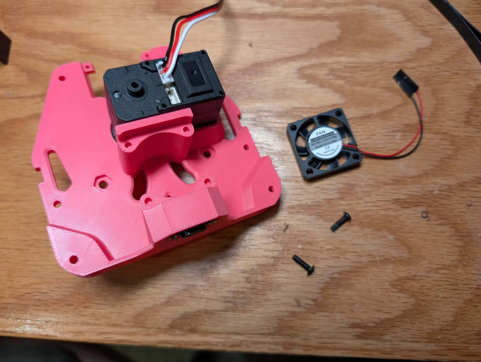
Attach a 30mm fan to the mechanism lid using two M3x8 screws in opposite corners. ensure the airflow points outwards.
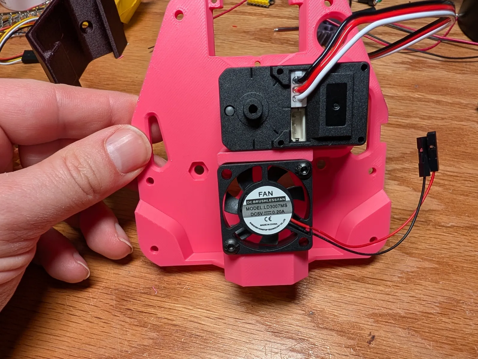
Plug in the Fan into to 5V socket labelled FAN on the gripper PCB.
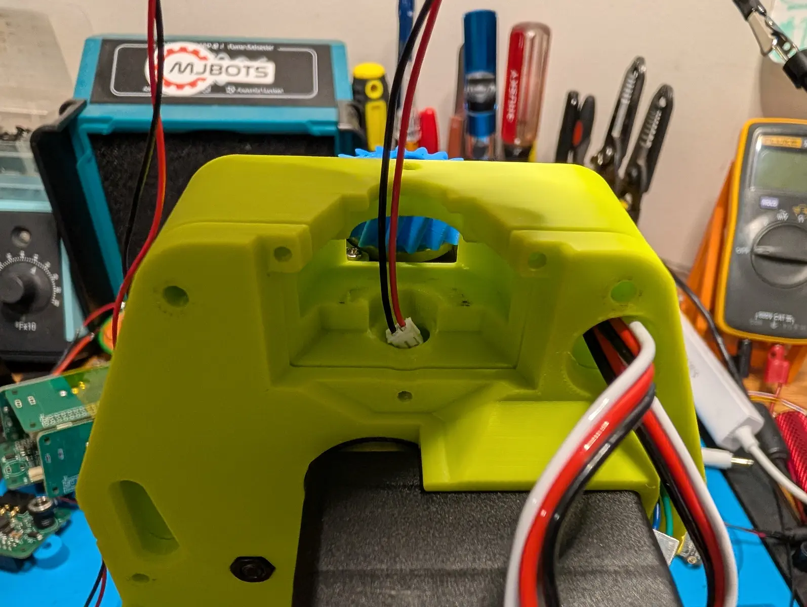
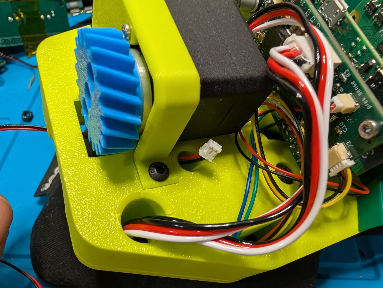
Unpack the 64cm cable with male JST ZH plugs at both ends. Thread it through the hole at the top of the gripper until it comes out of the body near the raspberry pi. Plug this into the socket marked 24v/GND on the Gripper Hat. Stuff a loop of slack from this wire of about 10cm into the other wires. This makes it the right length for the pole added later.

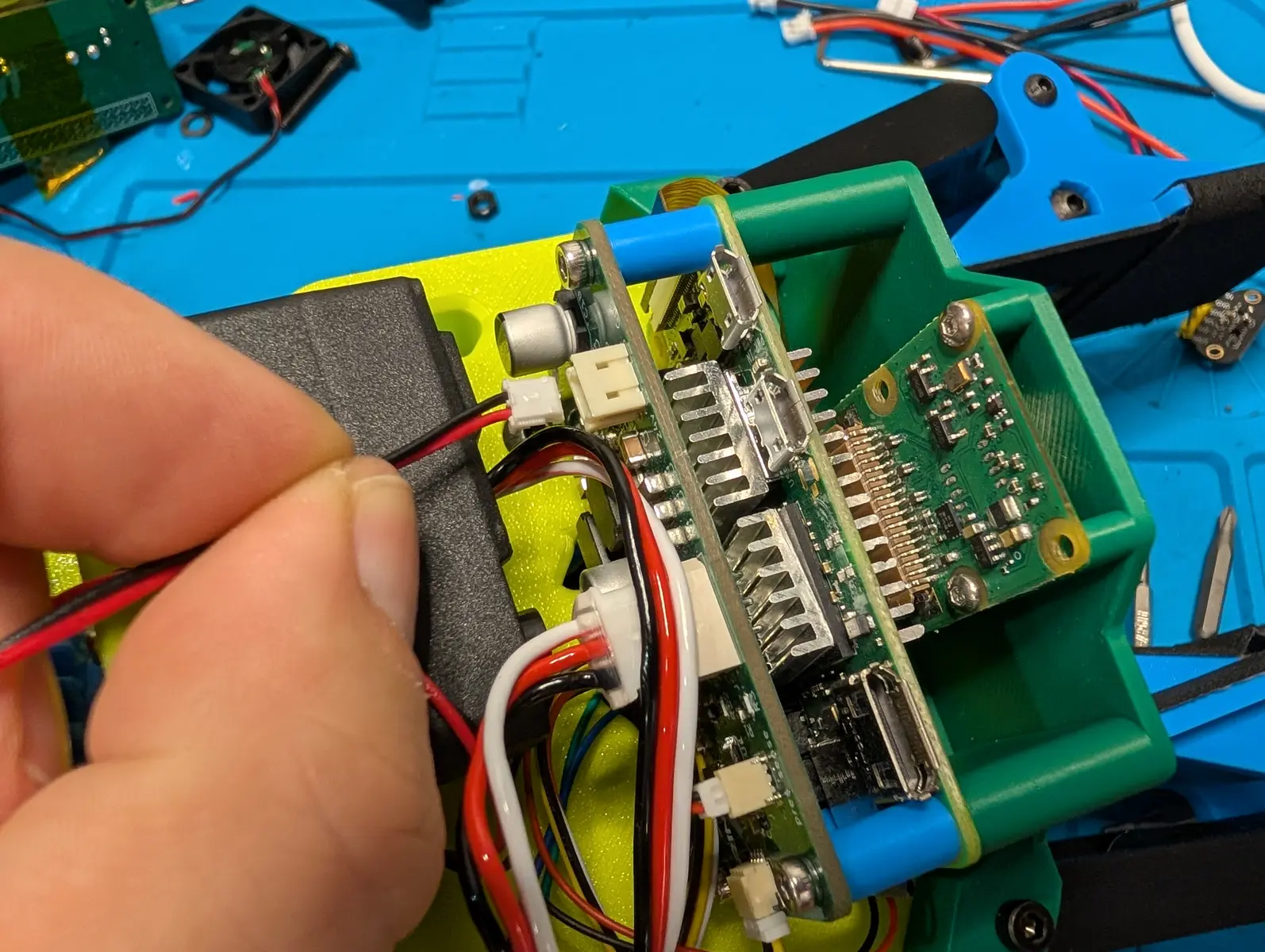
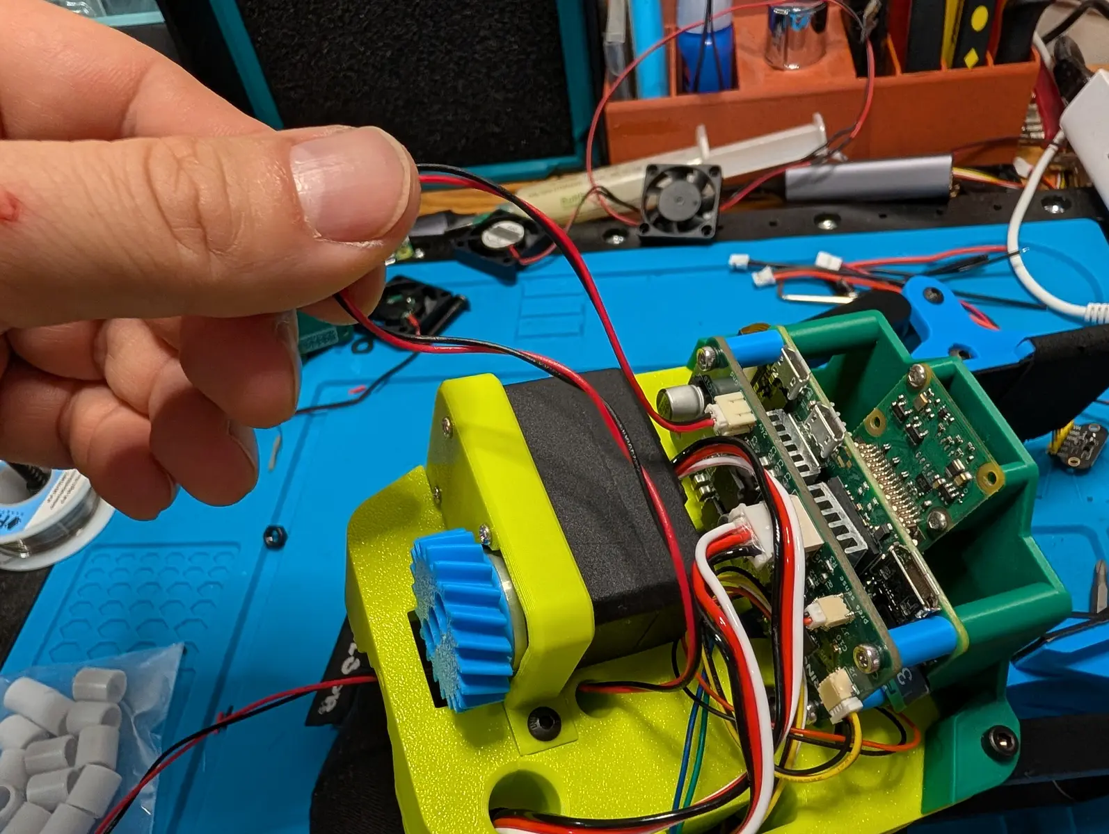
Marker Display Box
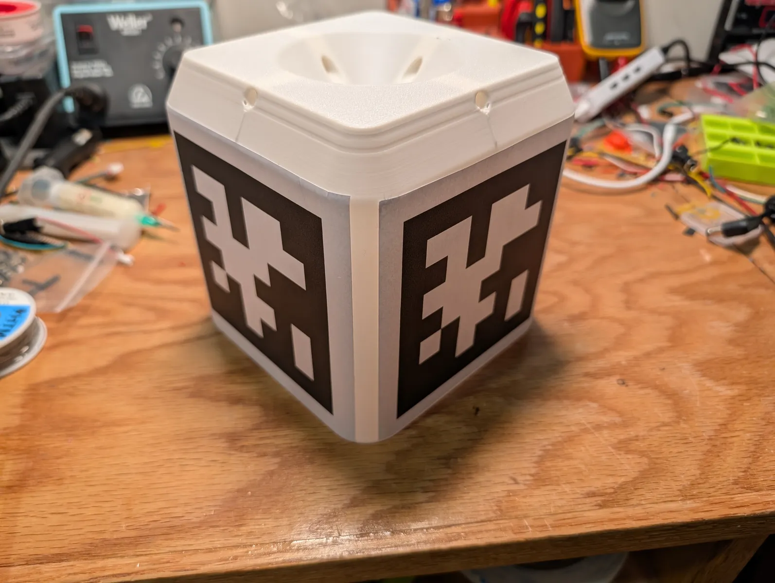
The marker display box is a passive component that displays april tags at the point where the lines meet. It was previously called the gantry and so you may find it referred to by that name.
Pole and Marker
The marker is a large apriltag attached at the top of the pole where Stringman's lateral lines meet. The marker is connected to the gripper by a 27cm carbon fiber tube with a diameter of 10mm. The tube can be cut to length either with a hacksaw or chop saw (slowly). Don't breath the dust.
Older ABS tube
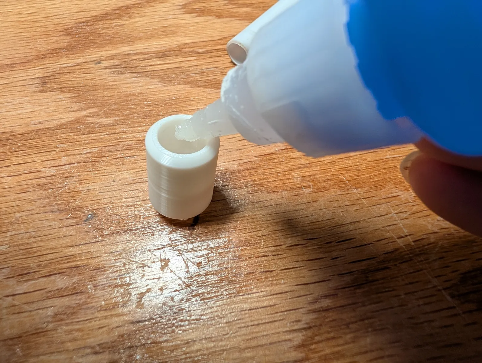
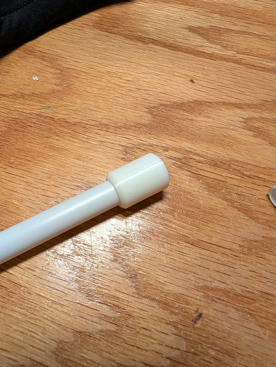
If you purchased a kit from Neufangled prior to August 8th 2026, you received an ABS pole cut in two. It needs to be recombined using a printed coupler. If you have the full pole, skip this step. This joint is the same type as that used at the ends of the pole. Apply JB Weld PlasticWeld Epoxy to a 1cm region at the end of a tube and press it into the coupler. Repeat with the other side.

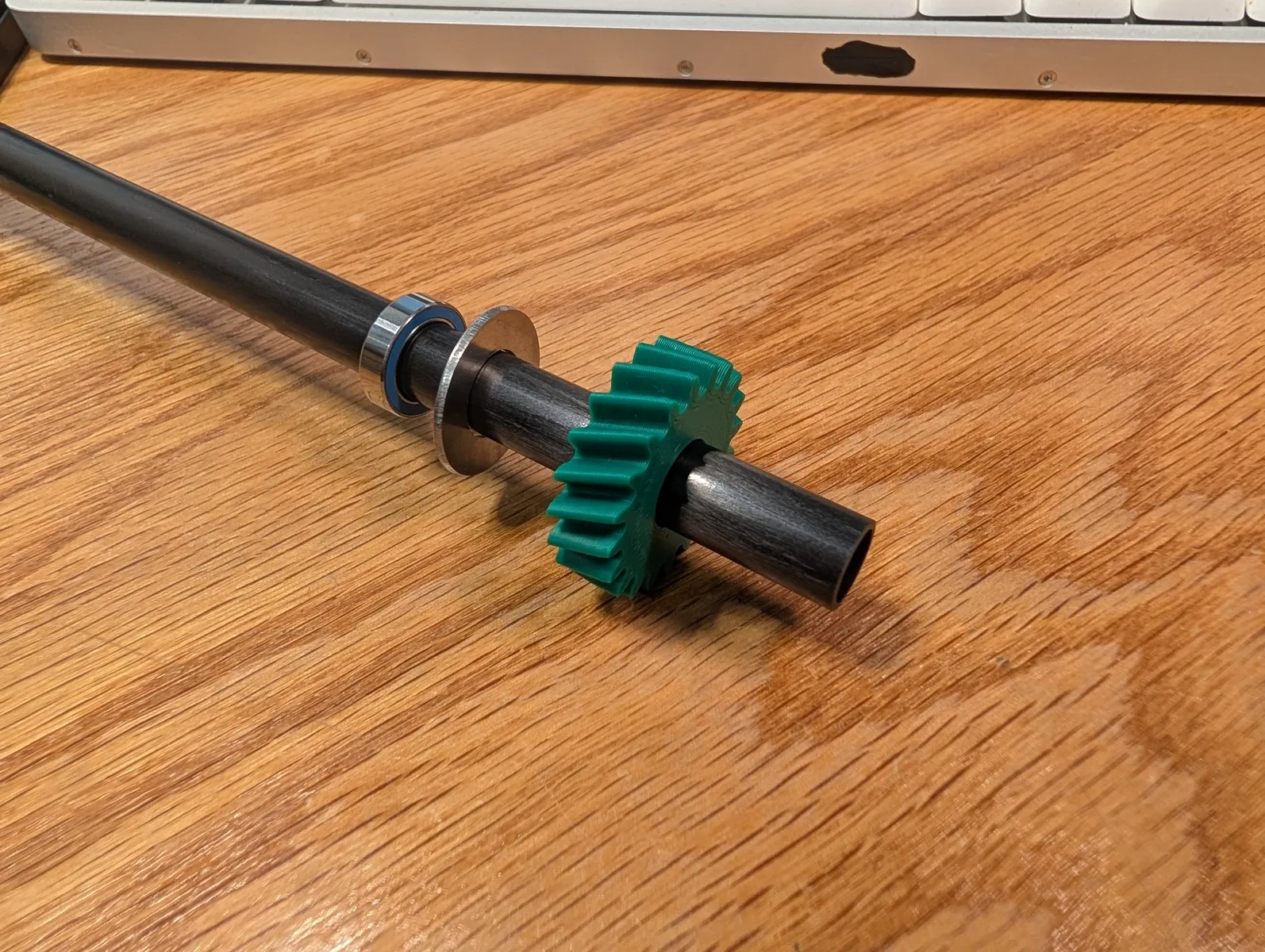
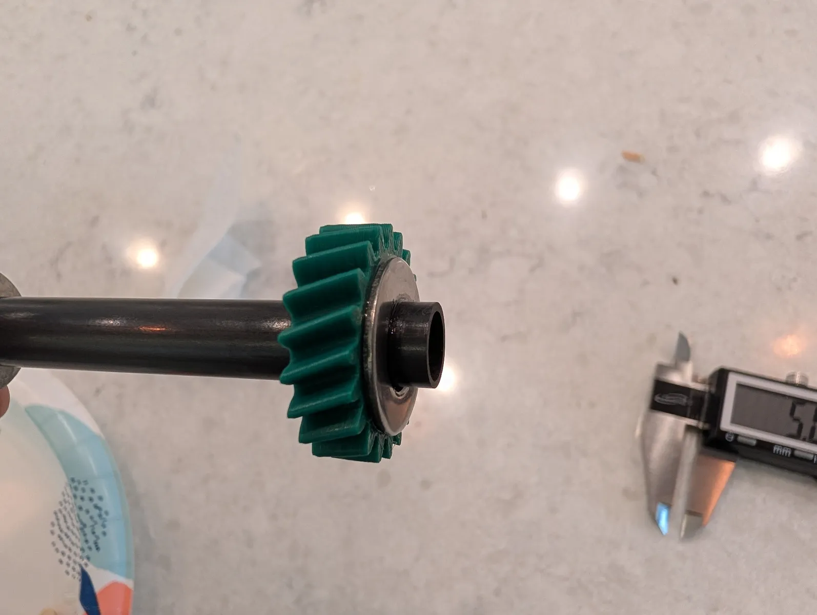
Put a 10x15x4 bearing onto the tube followed by a 3/8" x 7/8" steel washer.
Push and twist the helical gear onto the tube as shown until about 2cm of tube is protruding (not the final position, just leaving space)
Now the marker will be attached to the tube.
You can either print the marker in multi color for a more durable result or print it in white and add stickers.
If printing in multicolor, you can find it in the STL download in multicolor prints for bambu/flat_marker_colored.3mf
Print in white and black PLA
STLs are on the downloads page
If printing with a single color printer, print in white PLA then apply stickers to all sides.
This is the sticker paper on amazon and the document with the marker images is here. It must be printed without margins. The sticker for this part is "gantry" Cut the sticker sheet along the two grey lines to form two rectangular stickers of two tags each.
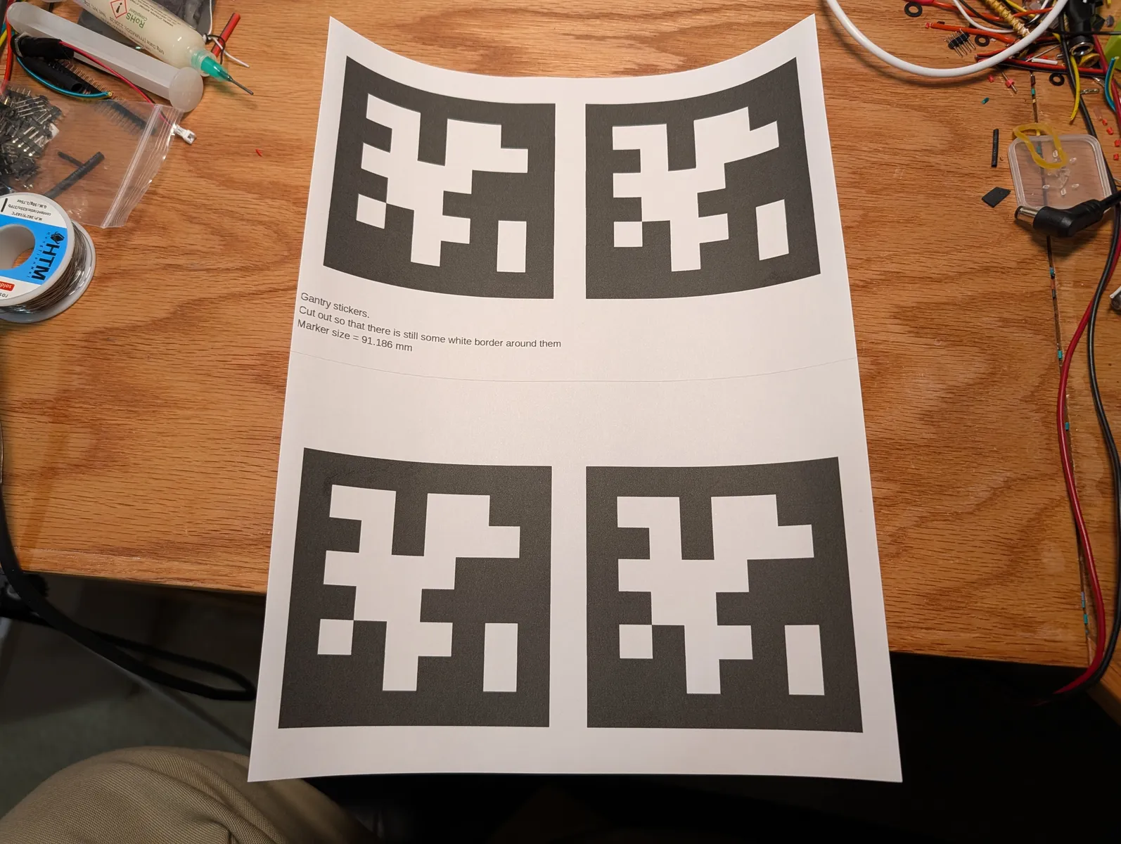

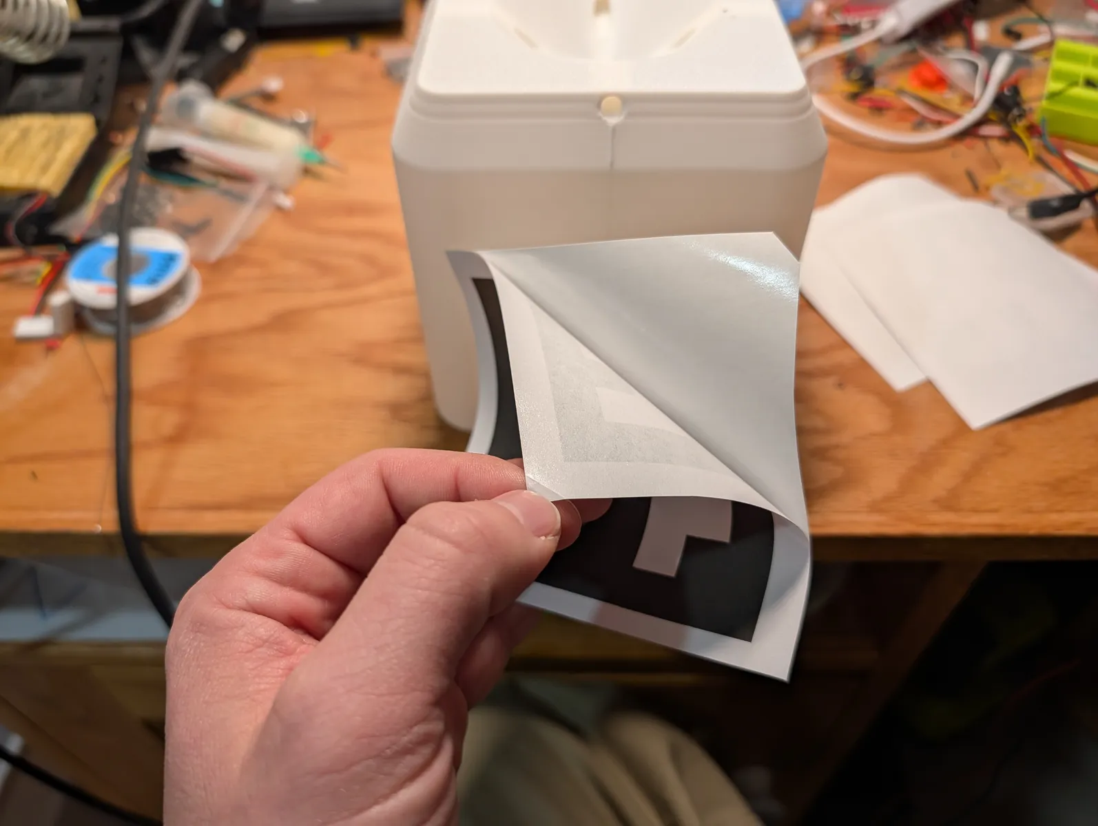
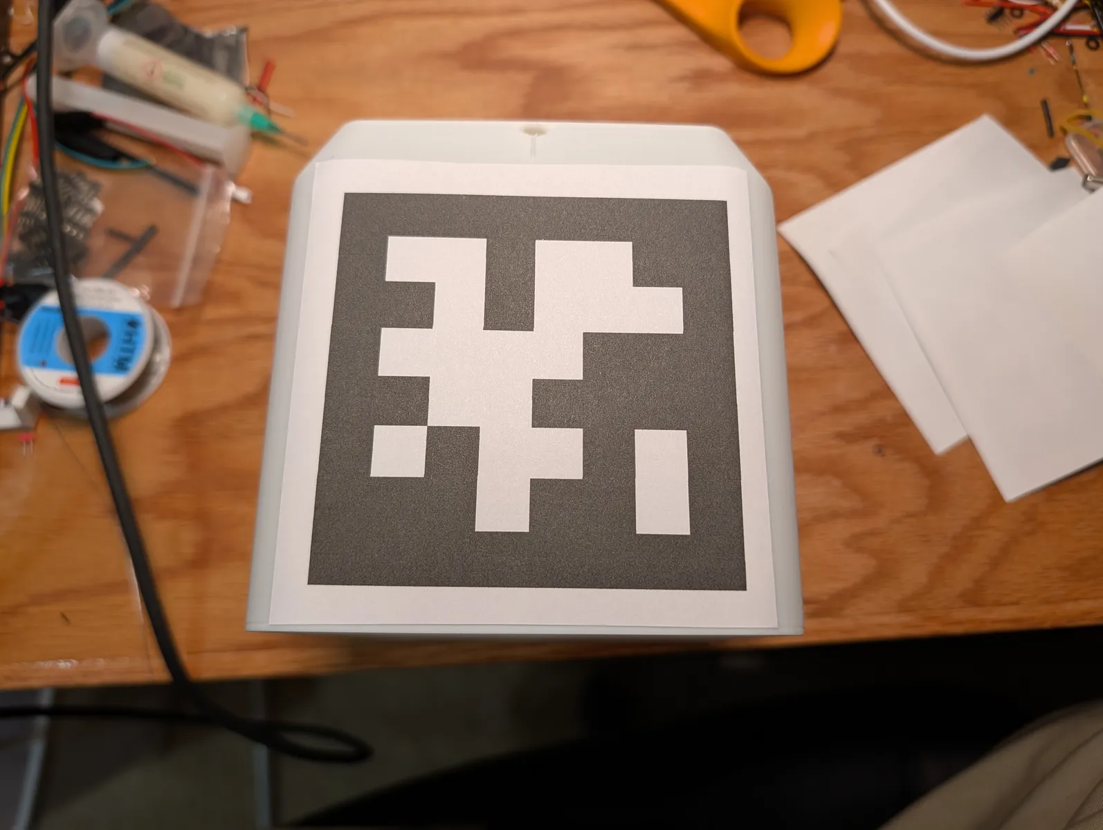
Score a triangle in a corner on the back of each one. This makes it easier to remove the backing. Pleace a sticker onto the box so it straddles one corner and a marker ends up on each face. Note the orientation, the "stem" of the tree is at the bottom.


Glue-up
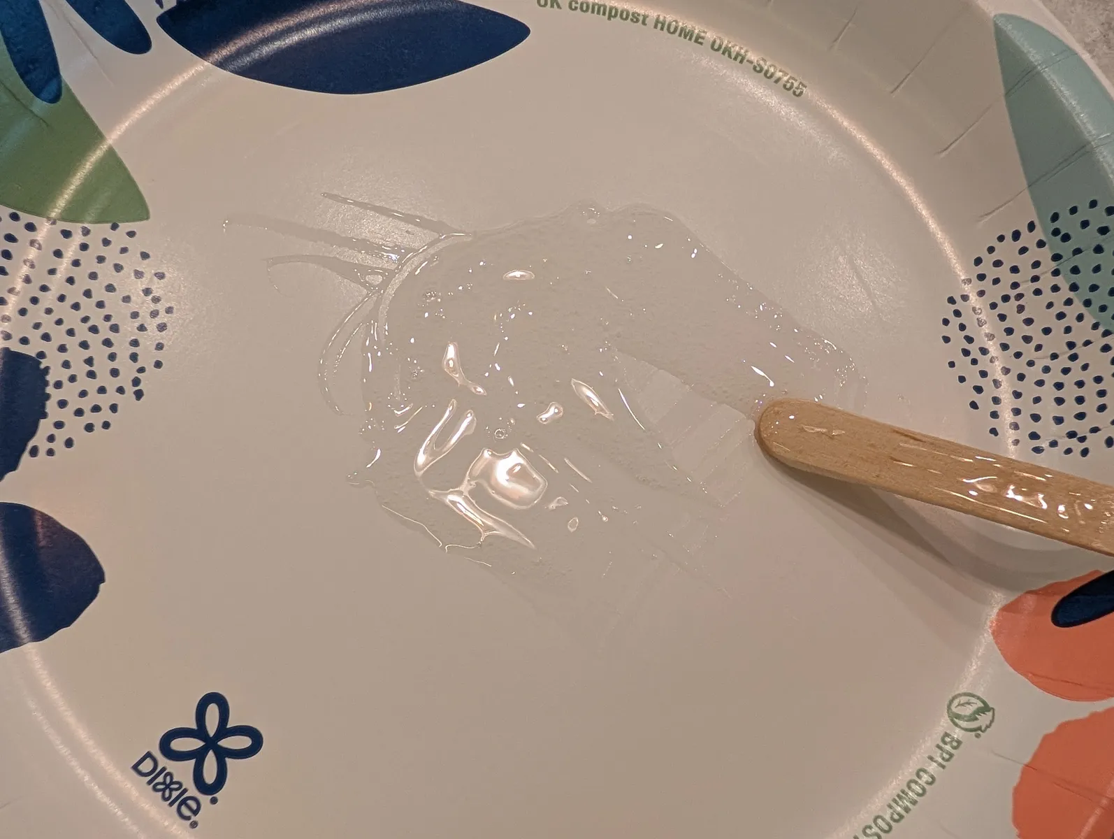
Prepare JB-weld Pasticweld Epoxy, a paper plate, a mixing stick, the pole with the gear in place, the marker and hang bar, and measuring device set to 5mm.

Mix a small batch of epoxy according to the instructions. Apply epoxy to the carbon tube below the gear.
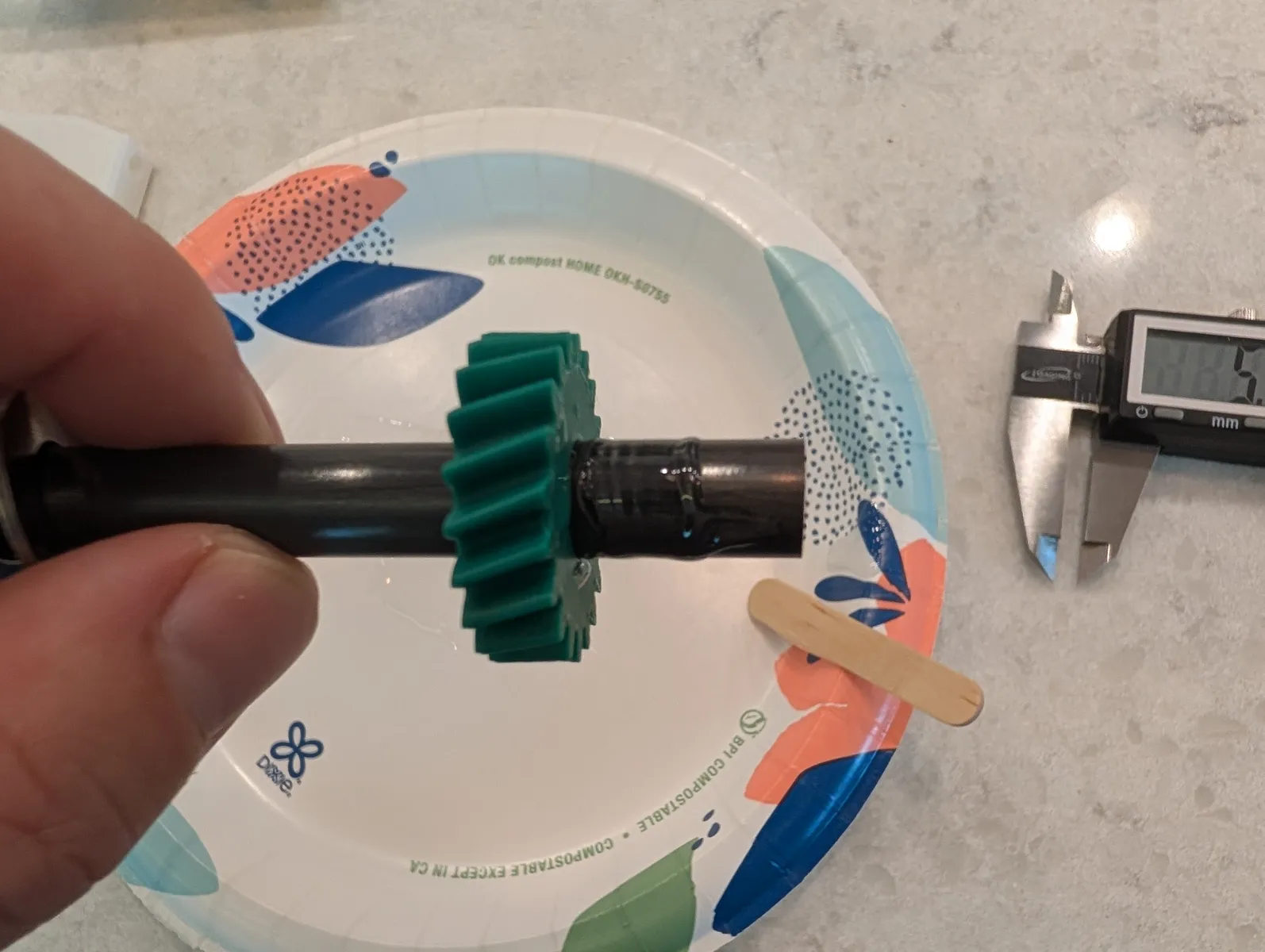
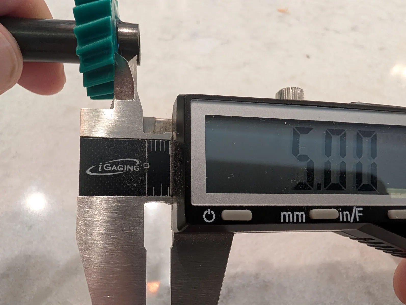
Slide the gear down until 5mm of tube remains. Place the last steel washer onto the end and stick it to the epoxy that squeezed out. Clean off excess epoxy.
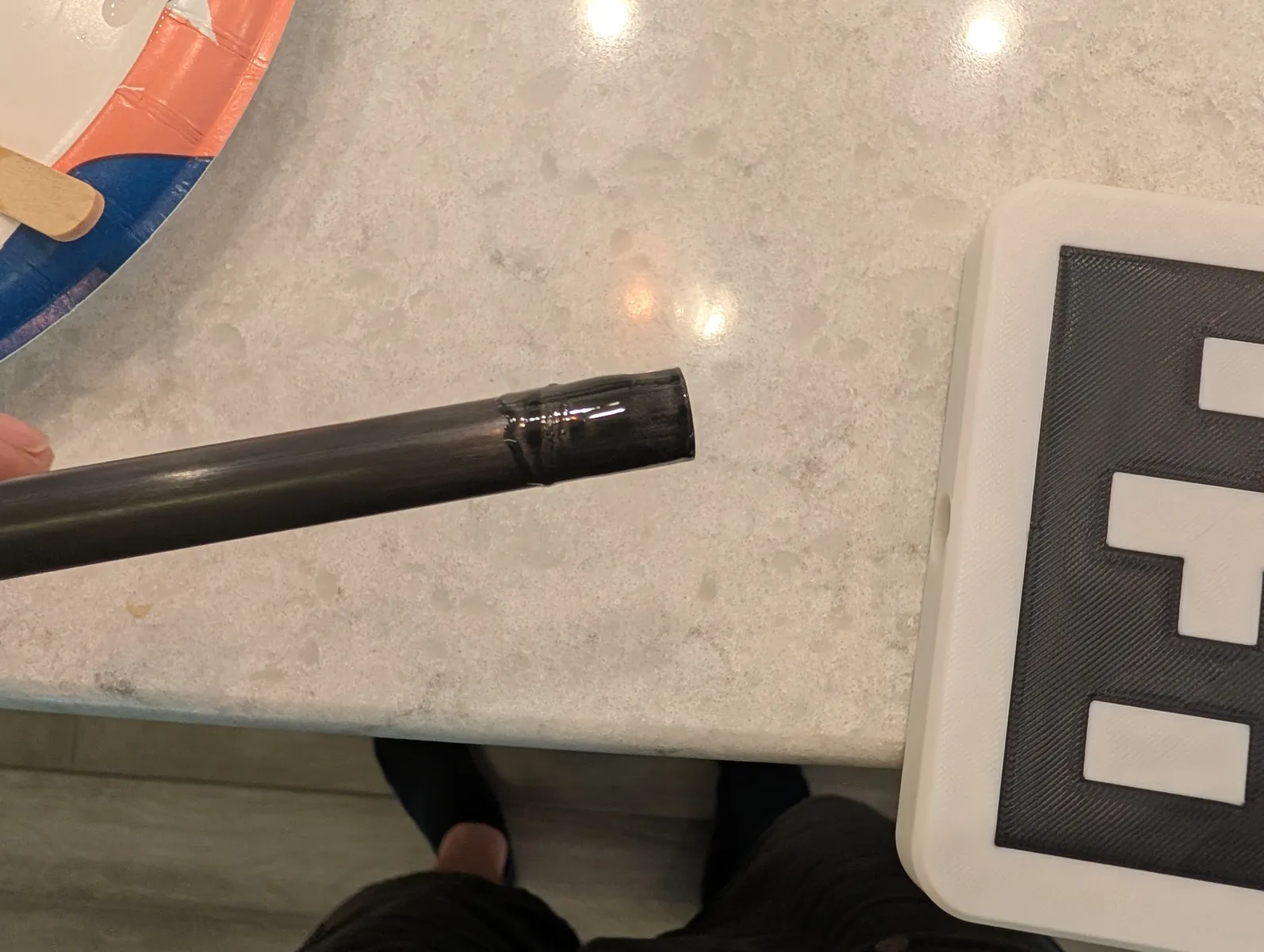
Apply epoxy to the top 3cm of the other end of the tube. Push it into the hole at the bottom fo the marker until fully seated. Clean off excess epoxy.
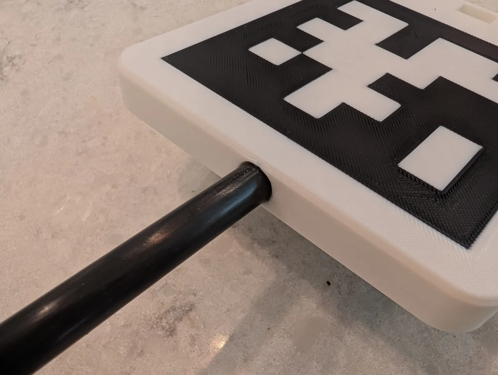
Insert the hang bar with the rounded corners facing down into the opening in the marker as shown. Almost push it all the way, apply some epoxy at the joint then push it all the way in. Allow these glue joints to cure for 24h.
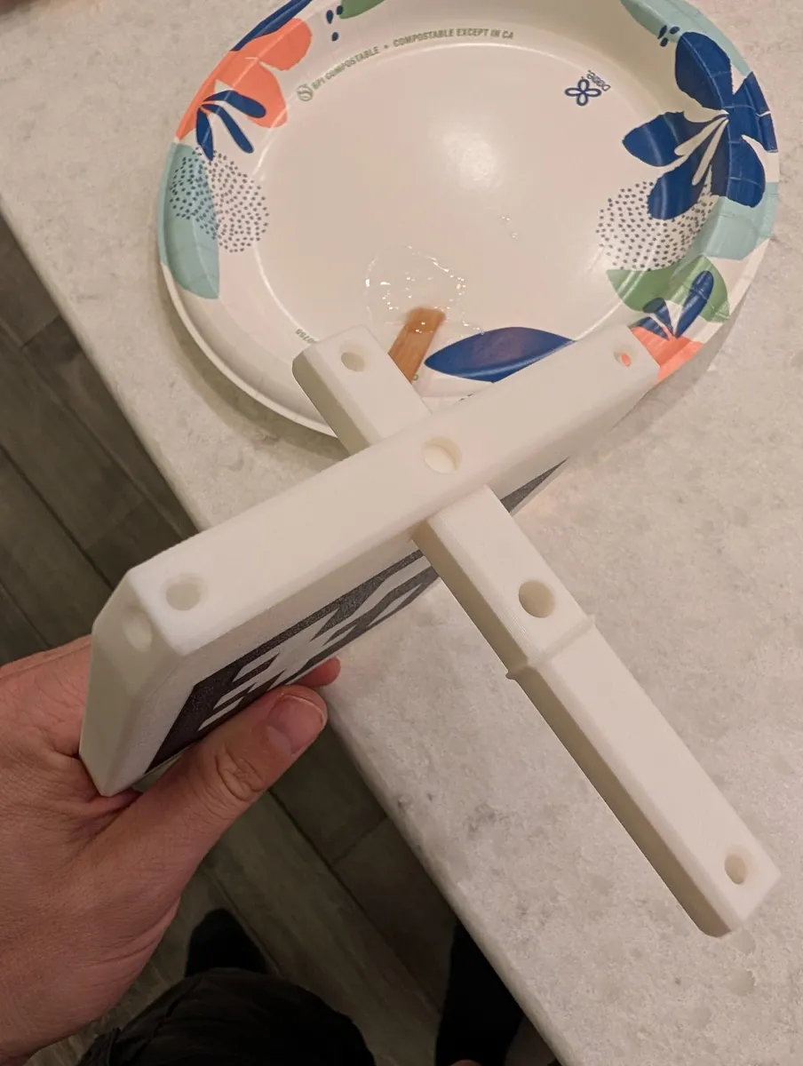
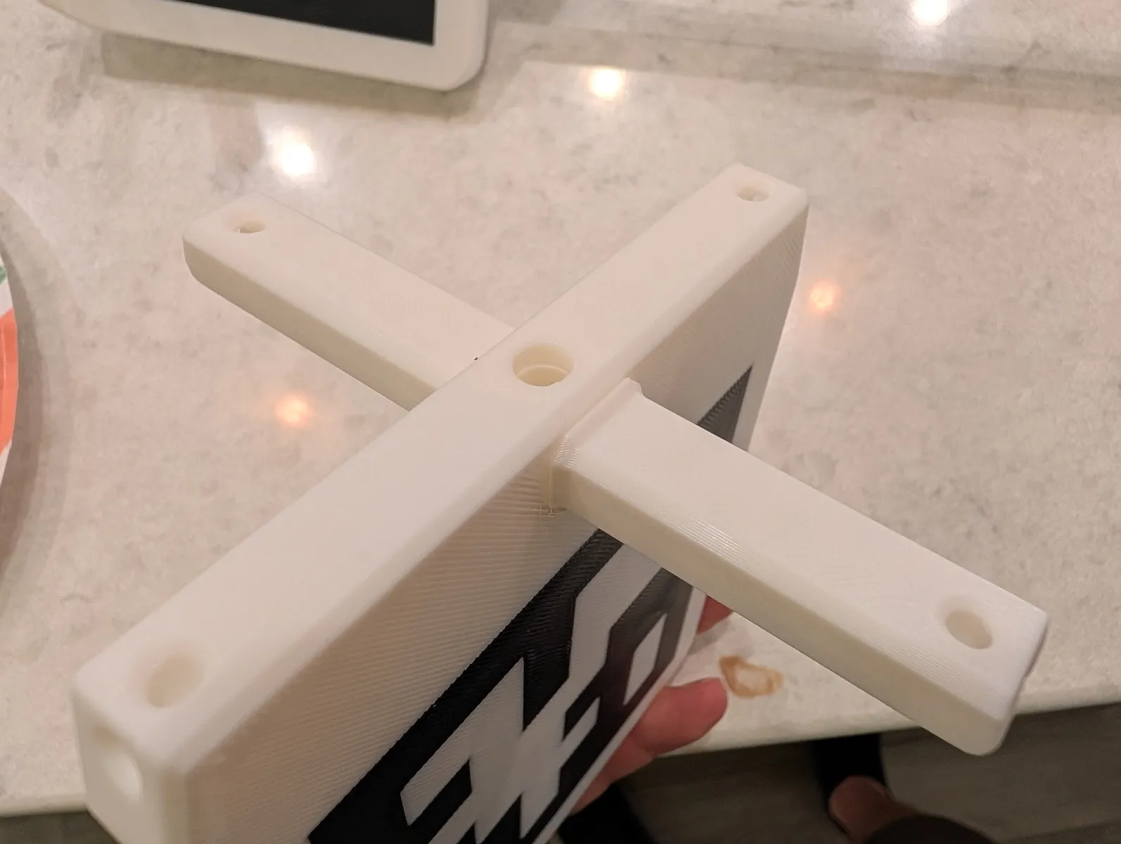
Completed marker and pole
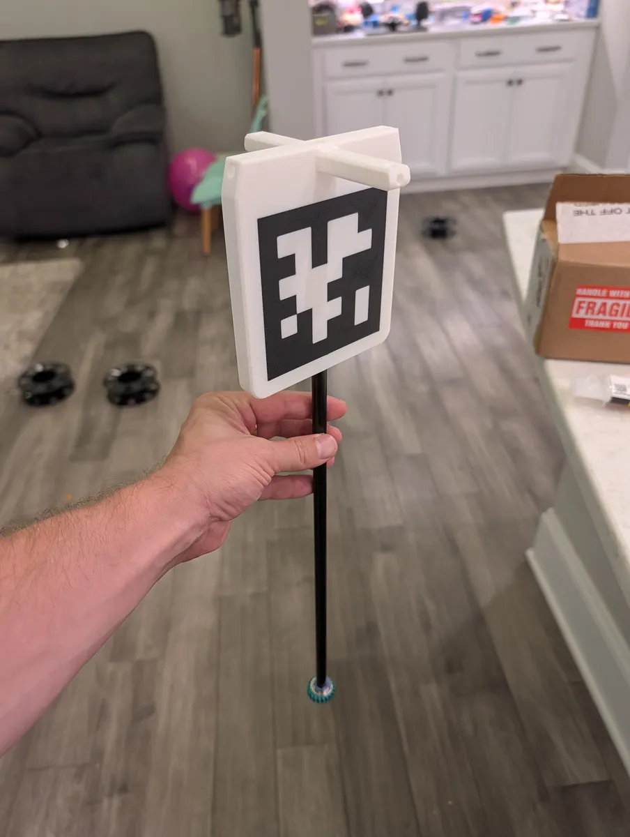
Attach the pole and marker to the gripper
Feed the power supply plug from the gripper up through the pole of the marker box until it comes out the top. If it gets hung up inside the tube, twist the tube back and forth and that tends to free it.
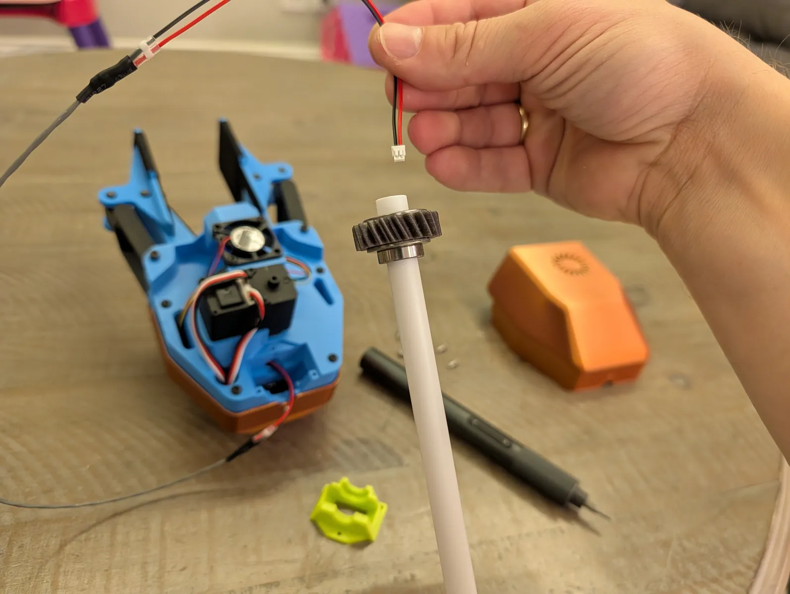
Seat the gear and bearing into the wrist socket. The rotation doesn't matter it will be determined later during calibration. Press the gear in until the teeth mesh and the bearing is fully seated, then press the wrist block down into the cavity and secure with three M2.5x6 screws.
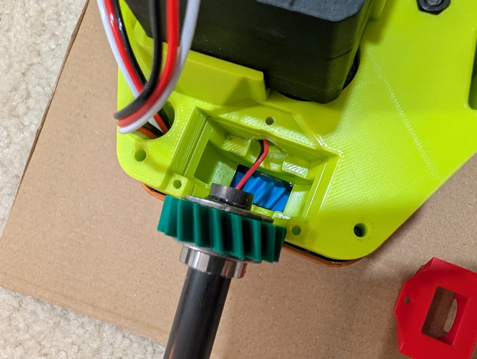
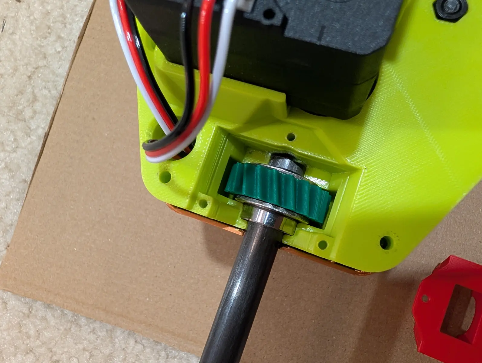
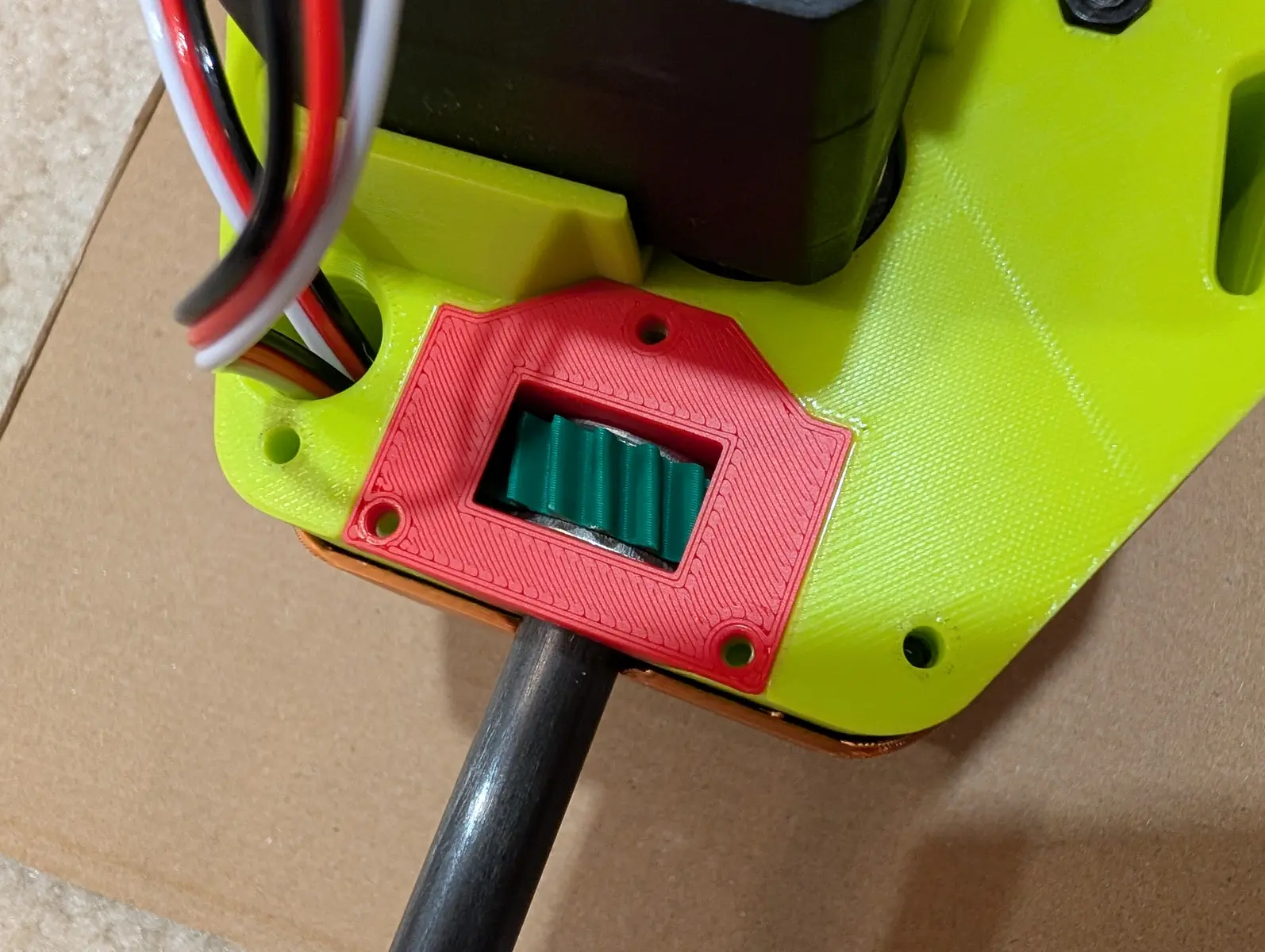
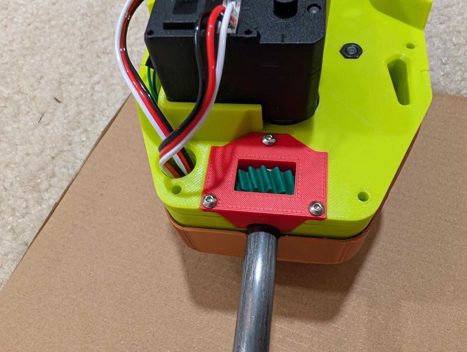
Install the front and back covers of the gripper with four M2.5x6 screws. Ensure the cover is pressed all the way on so that the camera's viewing hole is not obstructed.