Unboxing and Installation
Anchor Hardware Version: Arpeggio
Hardware installation of a preassembled or diy assembled Stringman pilot robot.
Tools needed:
- Step ladder
- Handheld drill/driver
- M1.5 hex bit (included)
- T20 torx bit (included)
Expected Difficulty:
- Takes 1 hour without interruptions
- Like hanging a curtain rod, plus at least 30 minutes for additional setup.
Hanging the robot in the room where it will operate involves installing anchors in two opposing corners, two eyelets in the other two corners, and attaching each of the four support lines to the gripper.
Video Guide
Planning
Choose two opposing corners to be the mounting locations for the anchors. The other two corners will be where you mount eyelets. The four-walled volume defined by these points is the robot's work area. It does not have to be rectilinear. If the room has a ceiling fan, you can mount the anchors and eyelets at blade height and they won't be able to touch. If the room has a bunk bed, it is OK to let it be in the work area but intelligent obstacle avoidances is not implemented so you might have to manually intervene sometimes.
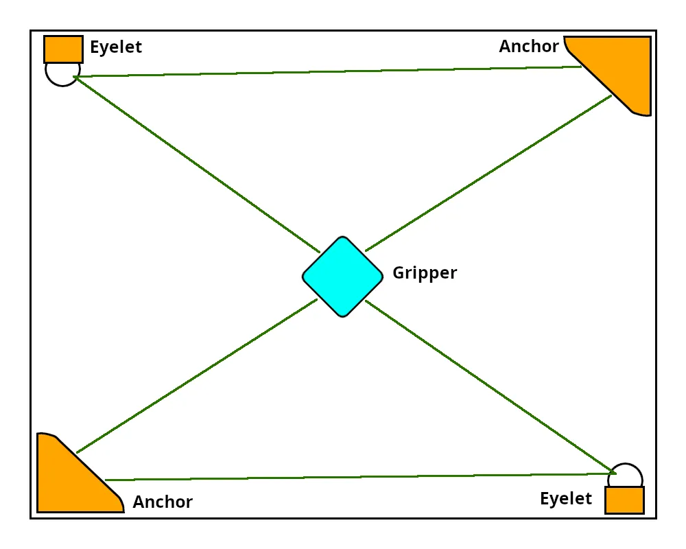
You must be able to mount anchors solidly to the walls
The only viable method of mouting stringman at this time is directly to the wooden studs behind the wall, or strapping to structural columns. If the walls of the room do not contain studs you can screw into, then you will have to install a backer-board that adapts to the room or ceiling's structural elements.
- Do not mount the anchors or eyelets with adhesive or magnets. Although there are command strips made for 5 kg loads, this is straight down. Stringman anchors will exert signifigant lateral loads in multiple directions.
- Do not mount the anchors to the T-bars of a drop ceiling, they aren't strong enough. The mount may not fail, but it may bend the T-bars out of shape and the changing orientaiton of the anchor would negatively impact calibration and swing cancellation.
You should try to maximize your work area by making the anchors and eyelets enclose the largest possible area that is free of obstacles.
Unpacking
Place each piece on it's front face on the bubble wrap.
If you received the pole and gripper in seperate pieces
Assemble gripper and marker box
The gripper and marker box with attached pole are separated during shipping in order to use a smaller box and must be assembled before use.
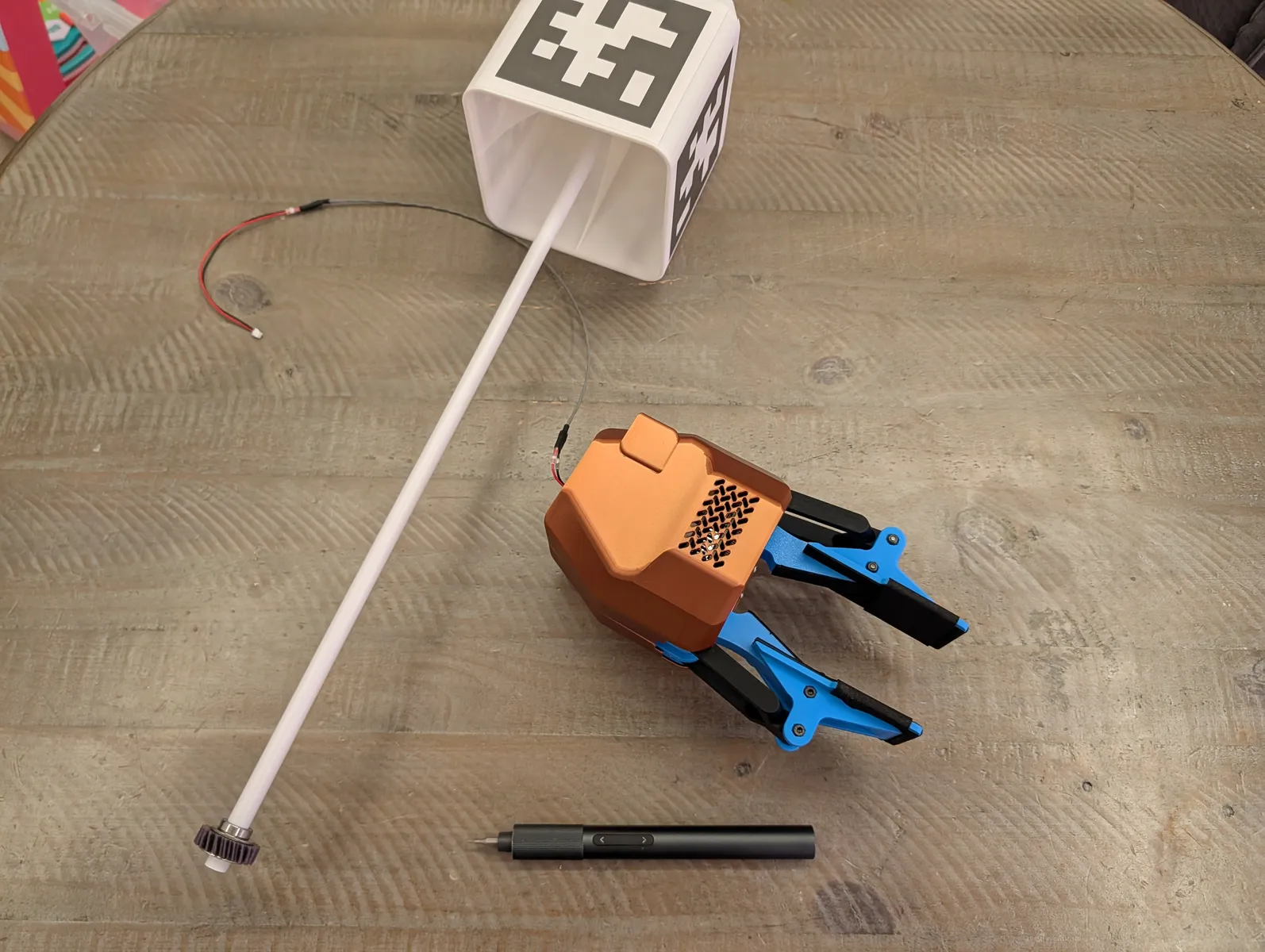
Using the provided 1.5mm mini screwdriver bit, remove the back cover of the gripper with two screws, one on top and one on the bottom. Your gripper may have been shipped with these removed already, in which case the screws can be found in the accessory bag.
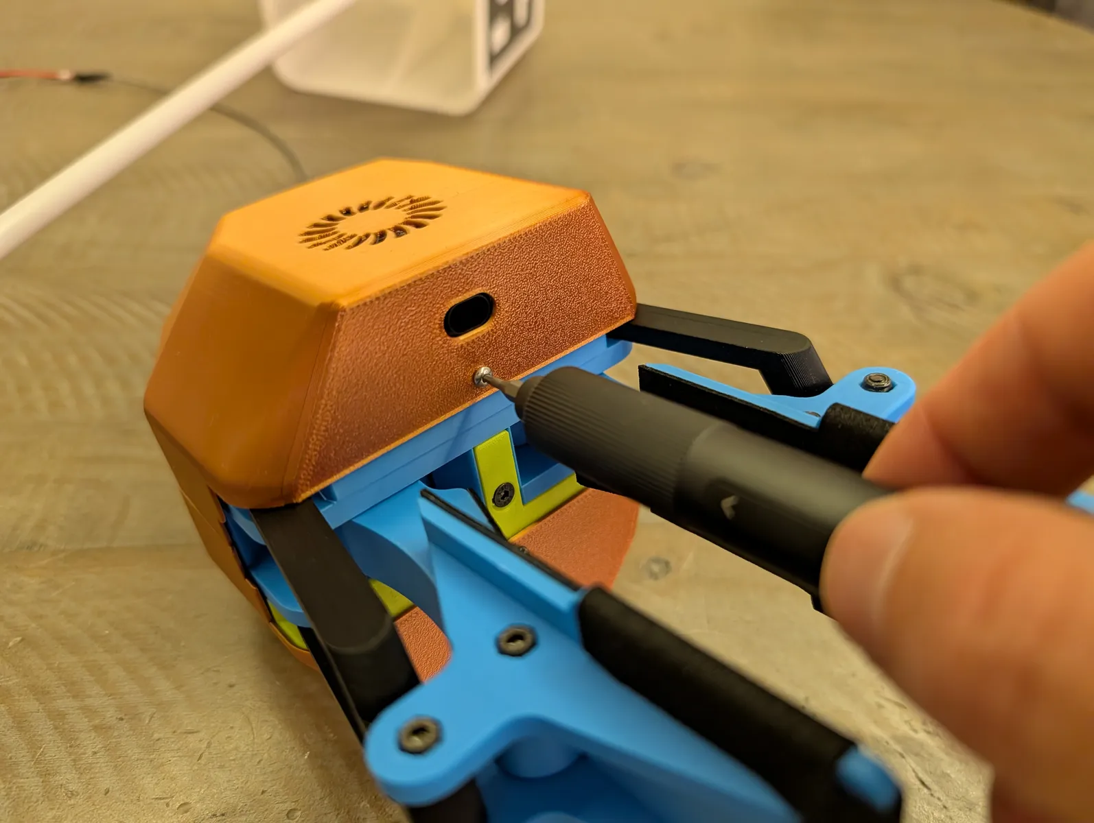
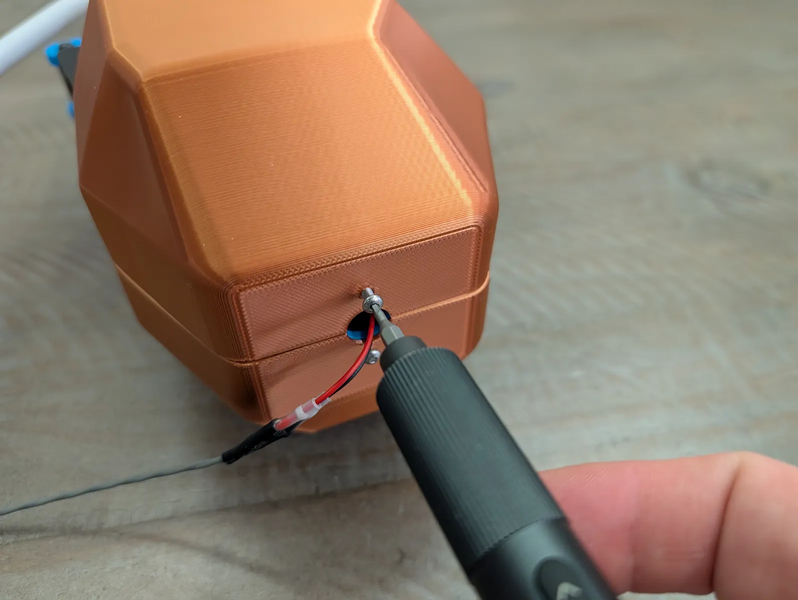
The block at the top of the back of the gripper with the rectangular hole is the wrist removal block. It securely holds the wrist joint. Color may vary on internal parts such as this. In these photo's it's lime green.
Unscrew the three screws holding it in and pull it out. It's intentionally a tight fit. If it's too tight, pry it out with a screwdriver.
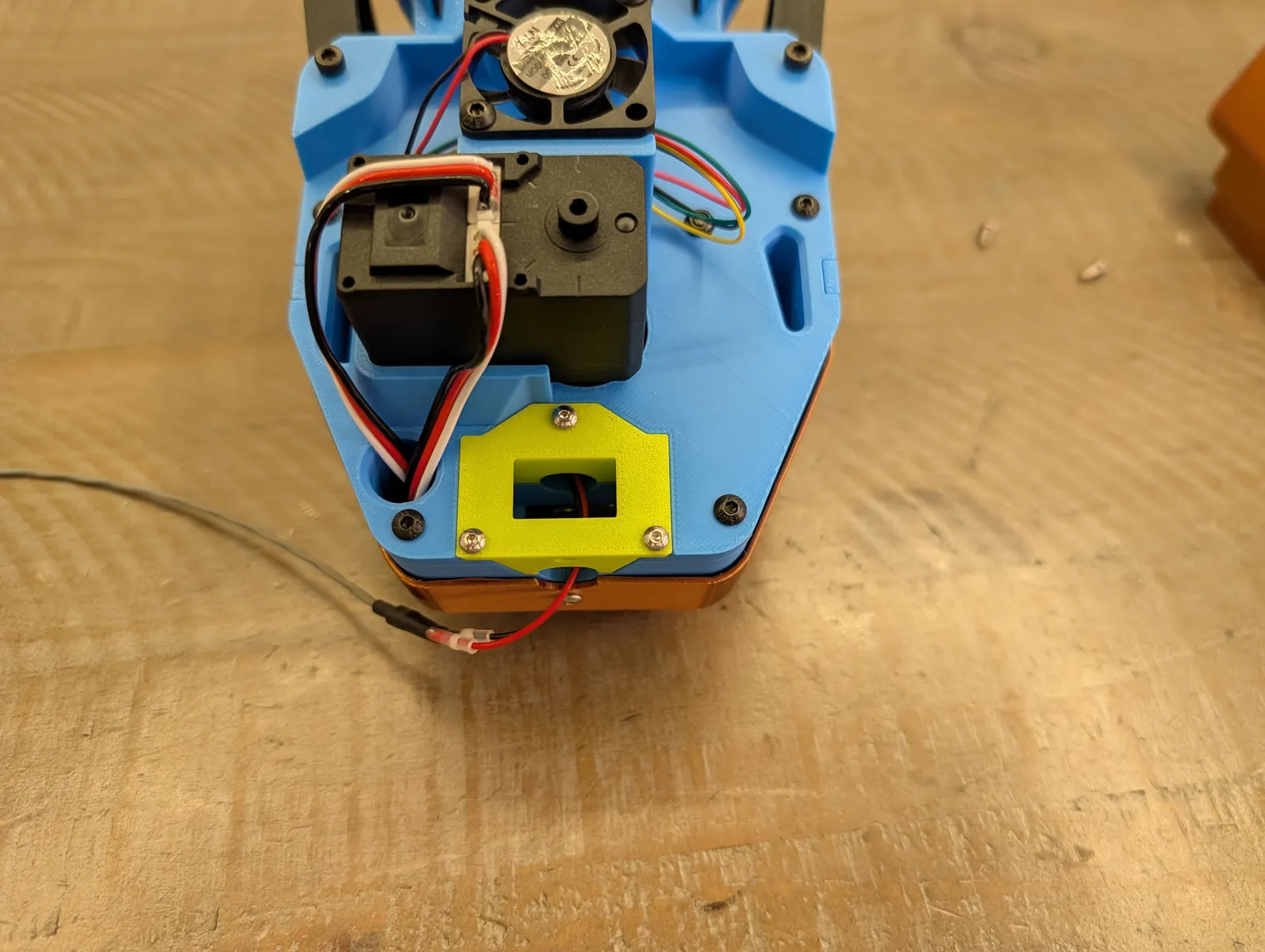
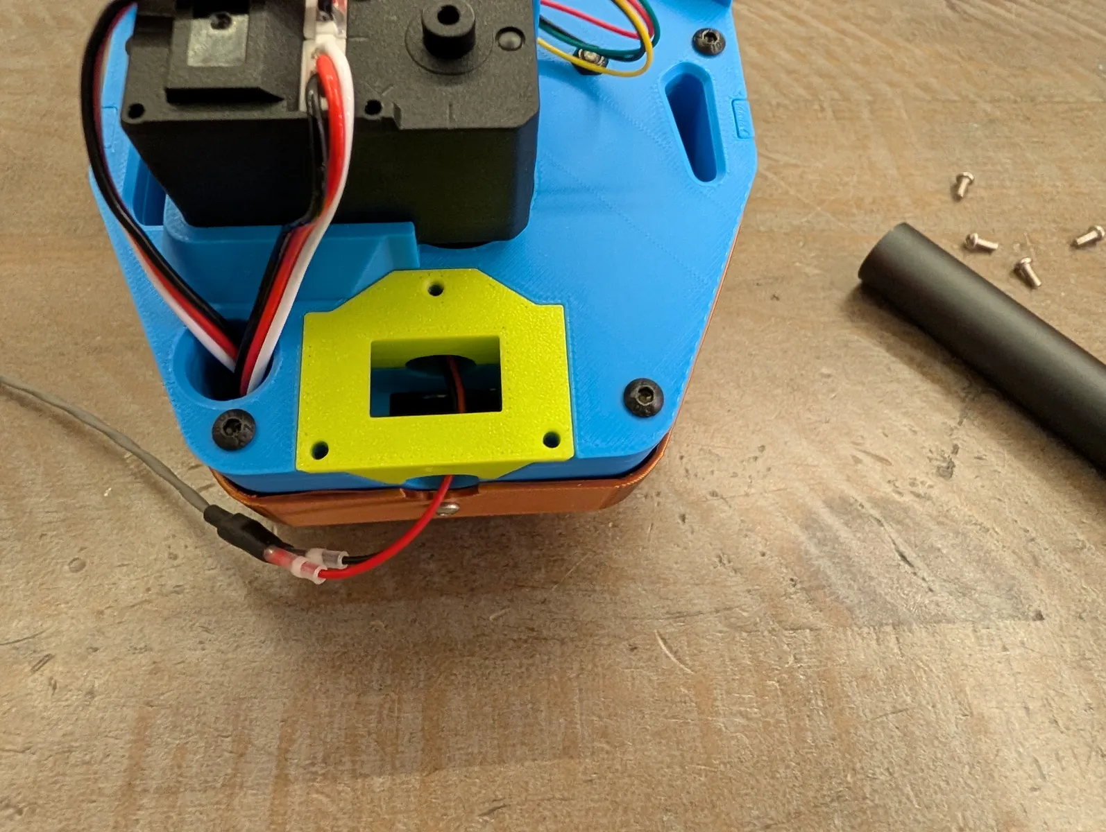
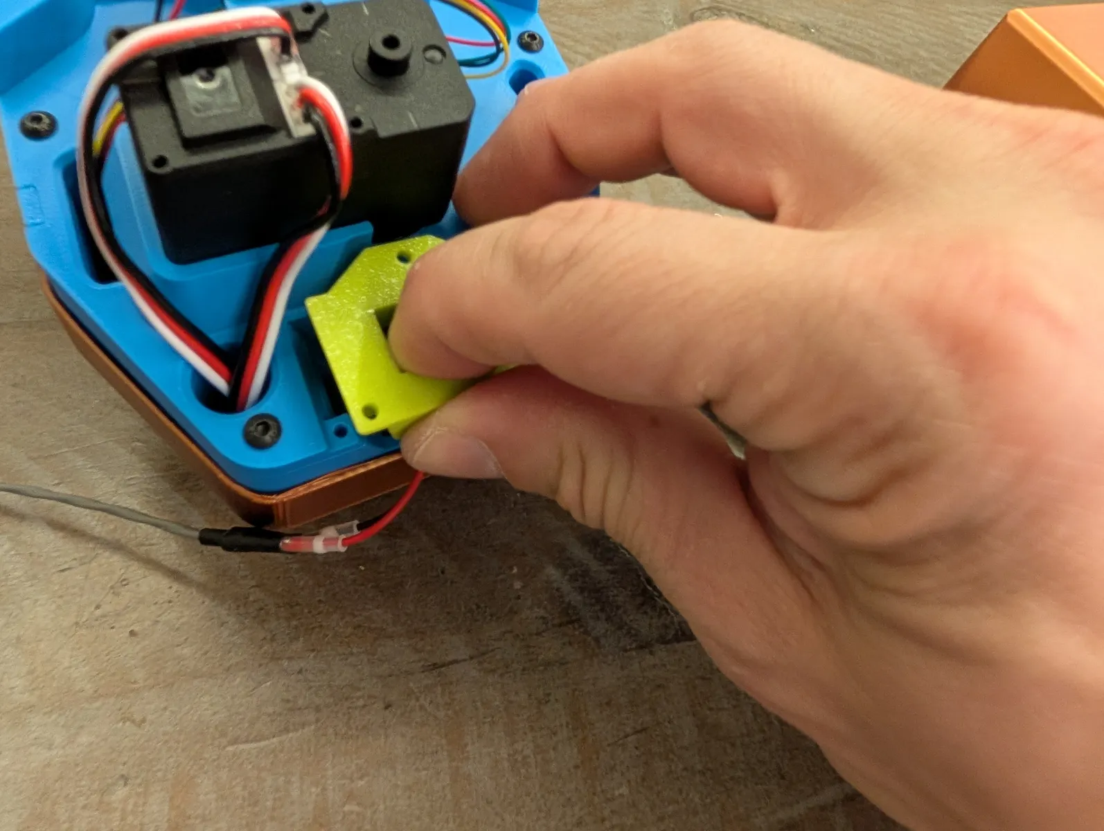
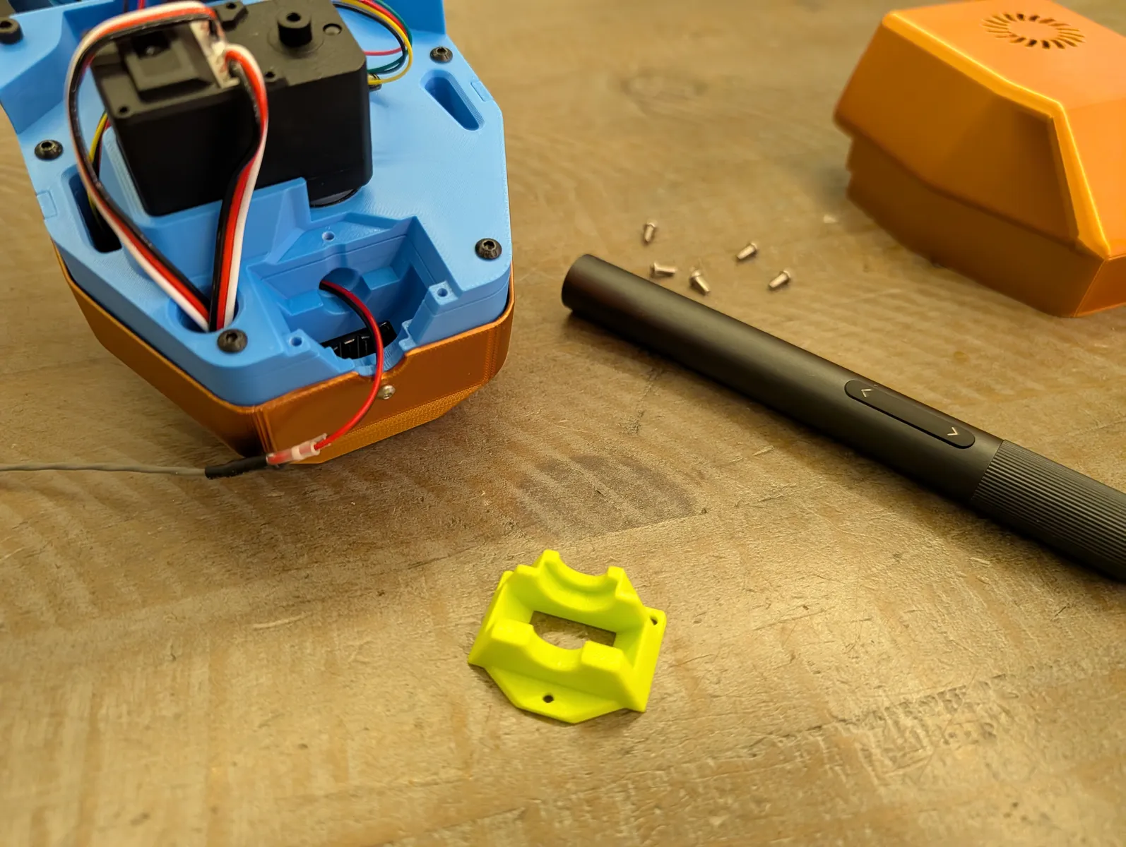
Feed the power supply plug from the gripper up through the pole of the marker box until it comes out the top. If it gets hung up inside the tube, twist the tube back and forth and that tends to free it.
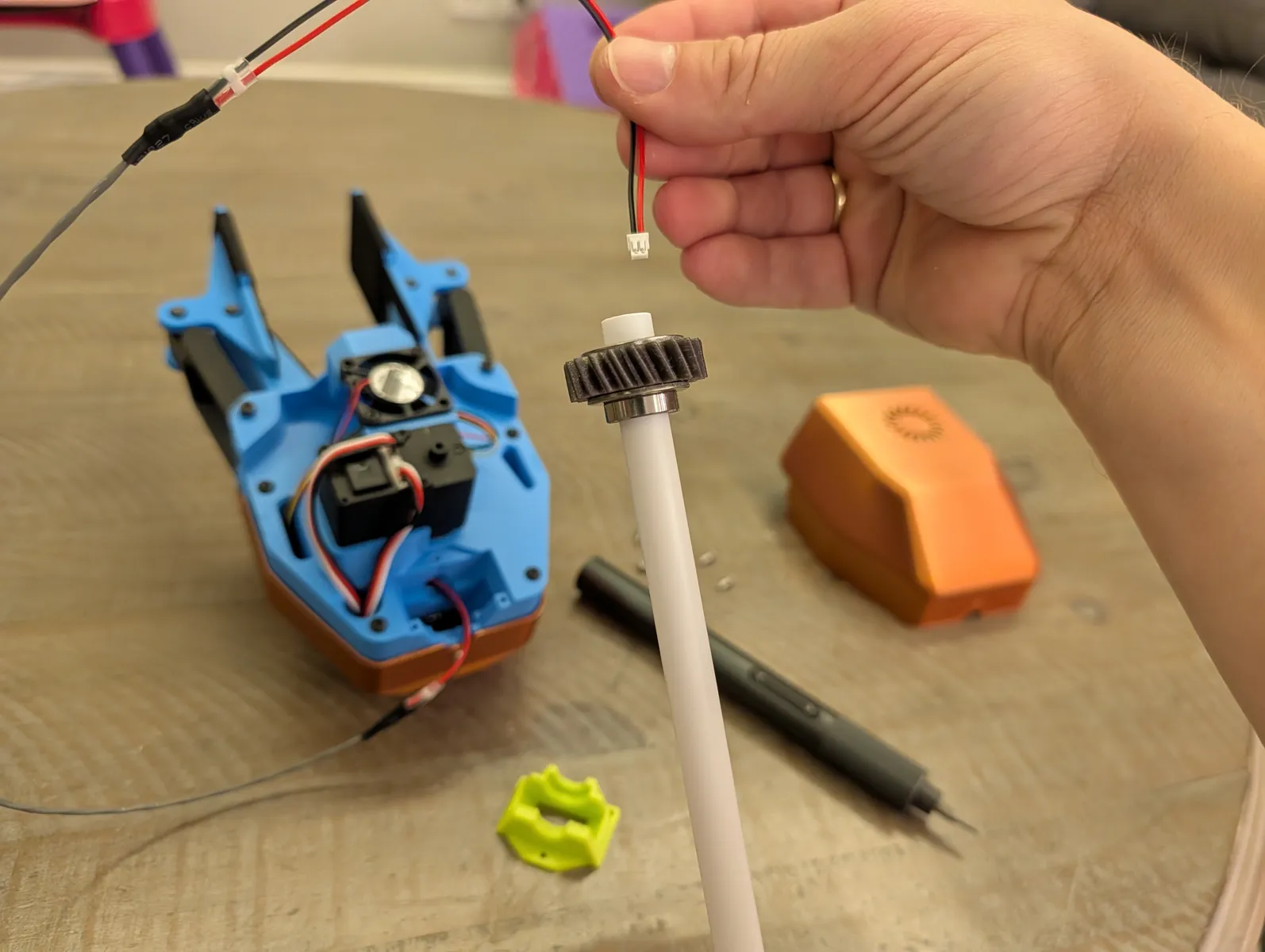
Seat the gear and bearing into the wrist socket. The rotation doesn't matter it will be determined later during calibration. Press the gear in until the teeth mesh and the bearing is fully seated, then press the wrist block down into the cavity and secure with the three screws.
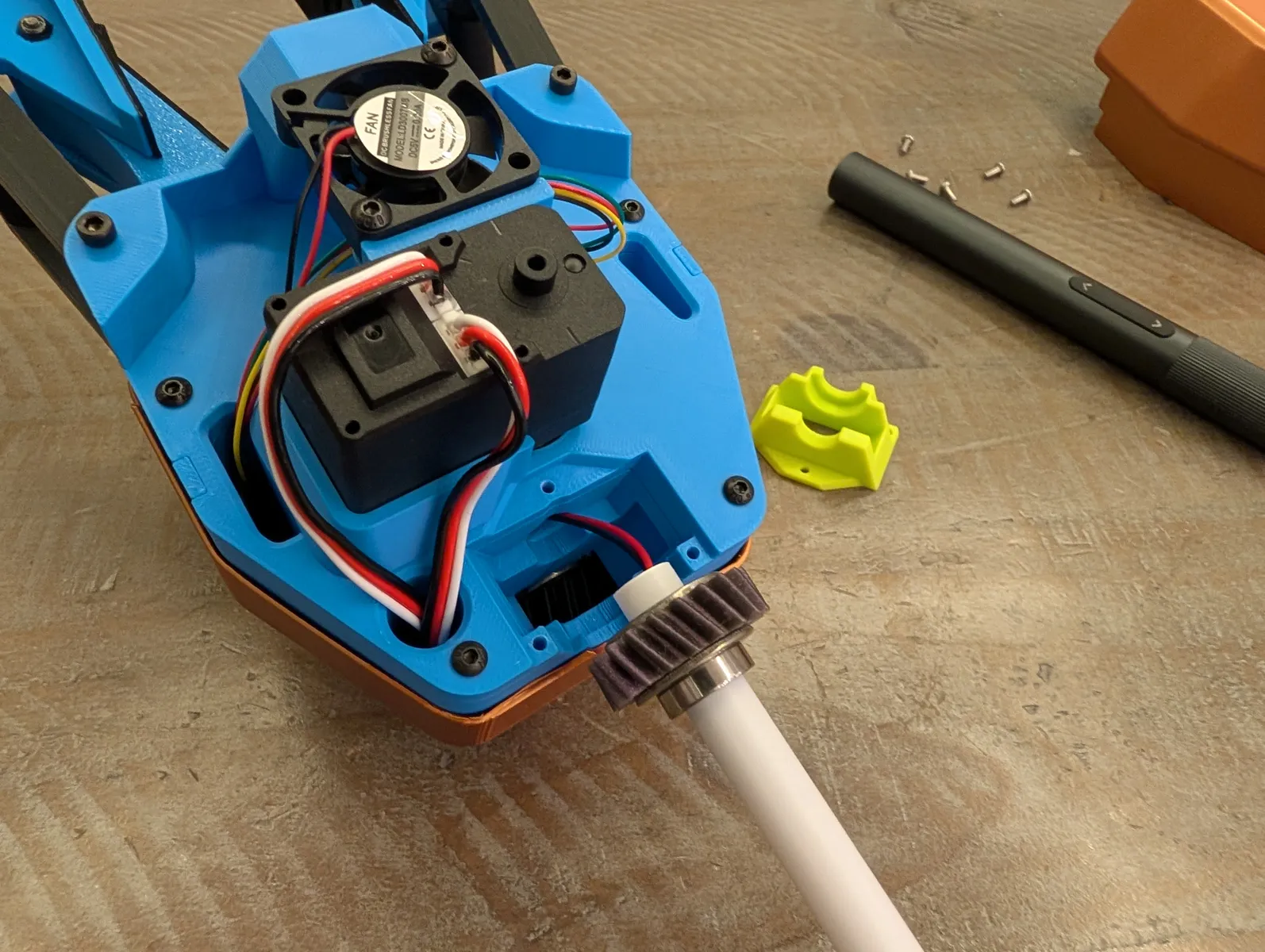
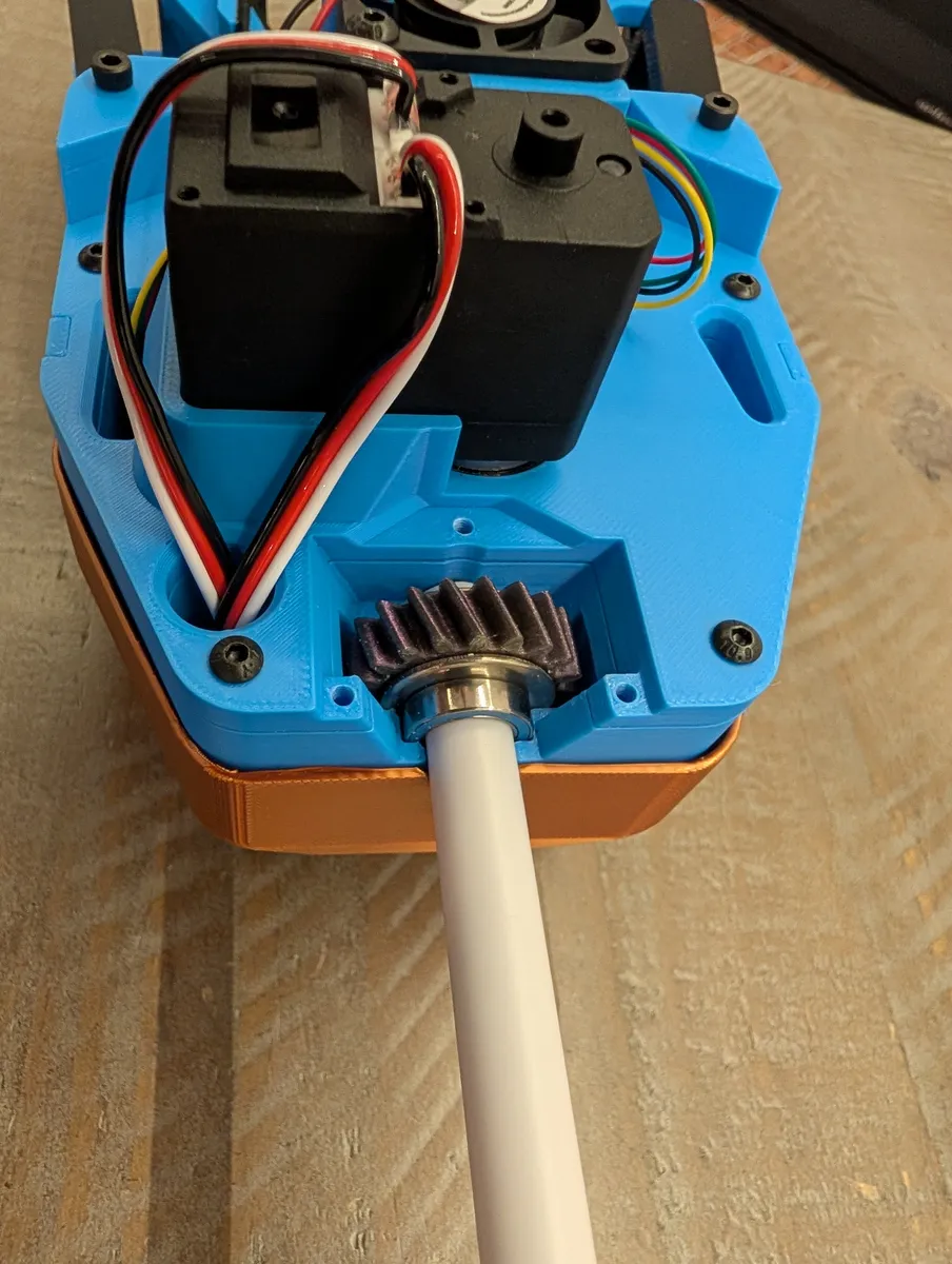
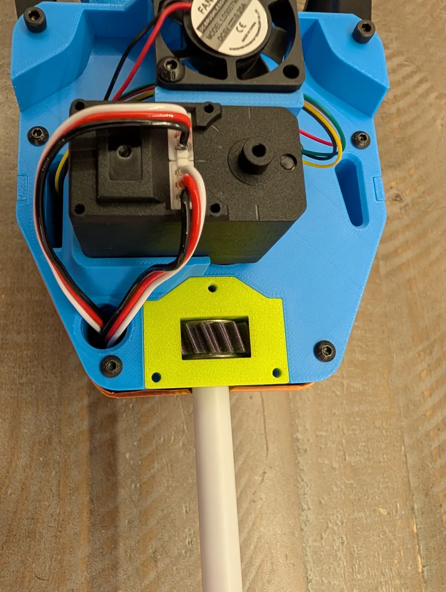
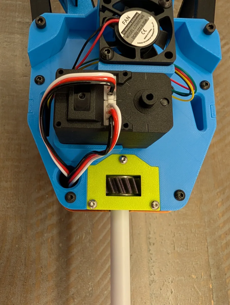
Reinstall the back cover of the gripper using the two previously removed screws. Set the gripper aside.
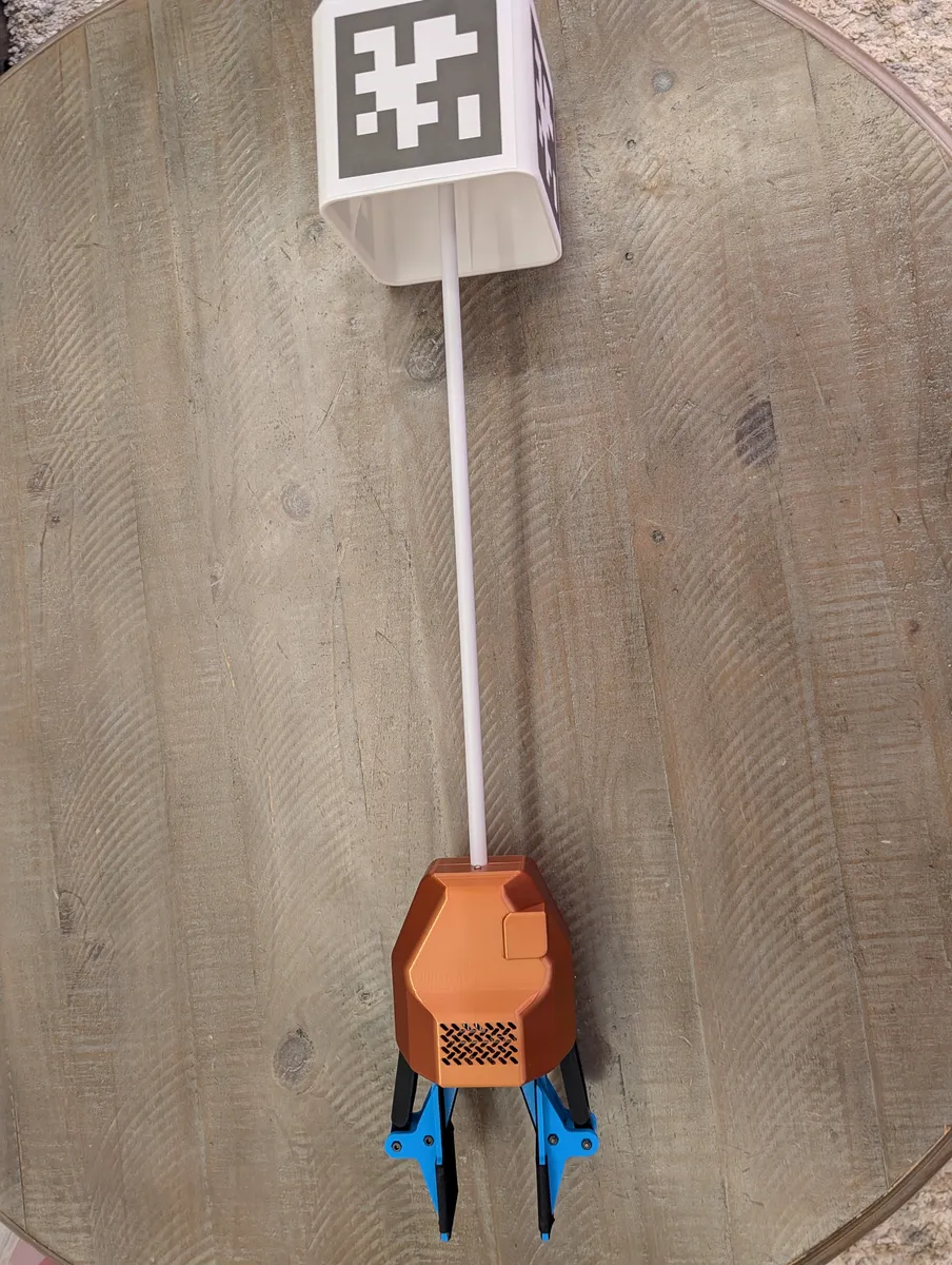
Mounting
Mounting Anchors
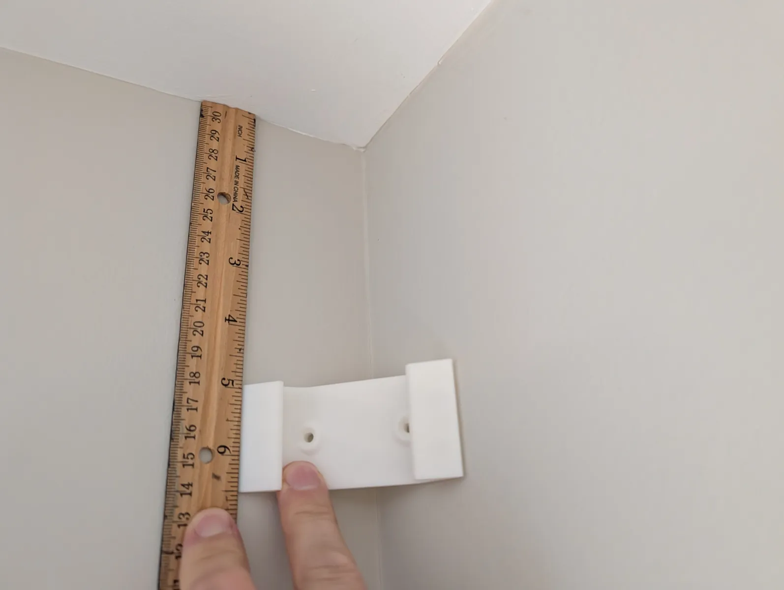
Mark 5 inches (13cm) below the ceiling on the wall in a corner where an anchor will be mounted. If there is crown moulding, measure 5 in (13 cm) below that. If there is a ceiling fan, mark the height of the blades of the ceiling fan. Take the lowest of these three options.
Place the stud_mount (butteryfly shaped) part against the wall with it's top edge at your mark.
If mounting in a corner, use the two horizontally centered holes of the stud mount. mark the holes and pre-drill them through the part, then drive in two 3 in (76 mm) wood screws. In a drywall finished home there is always at least one stud behind a wall corner. Hitting a stud on one side is sufficient. If you feel that you didn't hit any studs, the location may be unsuitable and require a backer board.
Many homes don't have very square walls. If the stud mount deforms when tightened against the wall, back off the screws until it's minimally deformed or you may not be able to slide the anchor onto it.
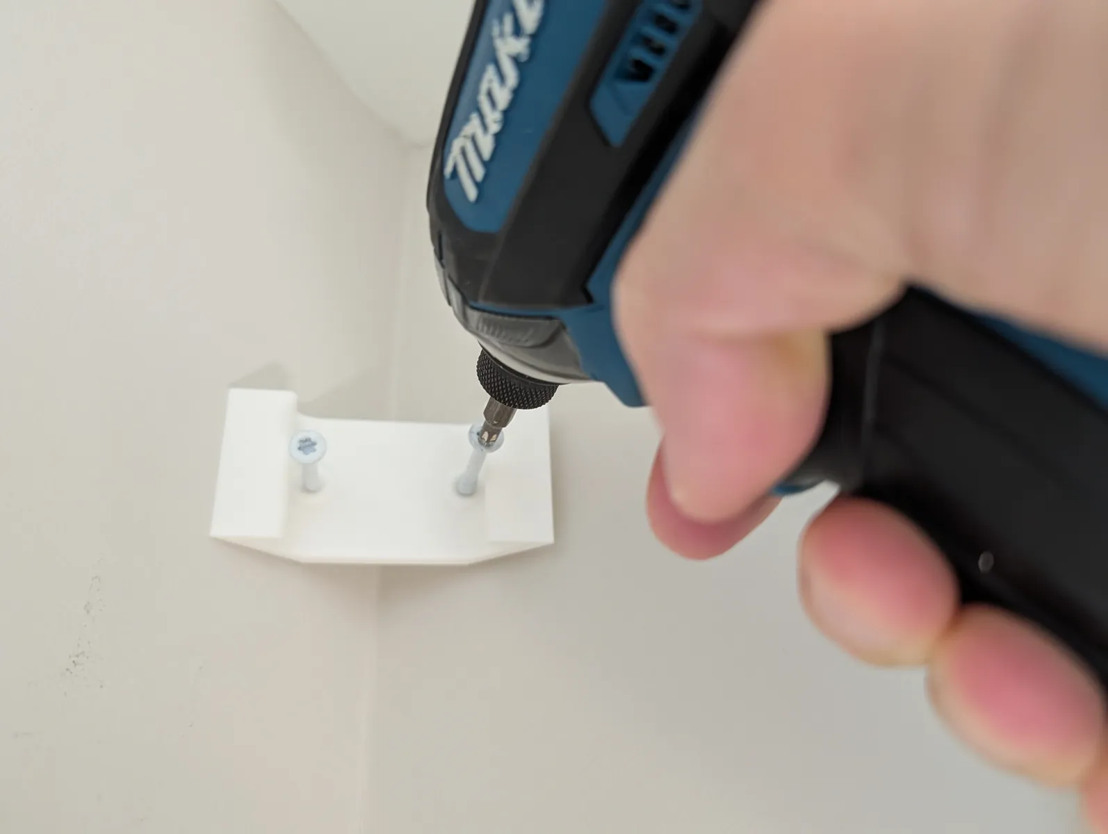
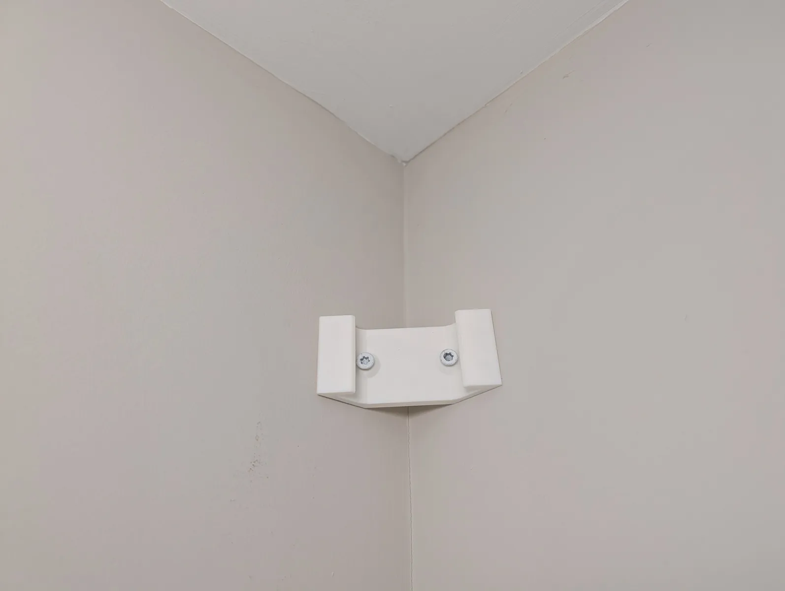
If mounting on a flat wall, use a pair of vertical holes on the same side so that the mount faces towards the center of the room as pictured. You must find a stud with a stud finder or other method such as spotting the drywall screws.
Hold the anchor up to the wall, near the ceiling. Slide it straight down in the corner so it engages with the mount and locks in.
Grasp it from top and bottom
Holding the anchor with the cover on can be tricky! It's easiest to clamp with both hands from top and bottom, but you can also remove the decorative cover on the ground and mount the anchor without cover so it's easier to handle. Then add the cover afterwards. It adds a step but it's probably safer.
While the ladder is still in place in this corner, plug in one of the white barrel jack extension cords and leave it hanging. Pull both lines out of the anchor down to a level where you can reach them without the ladder.
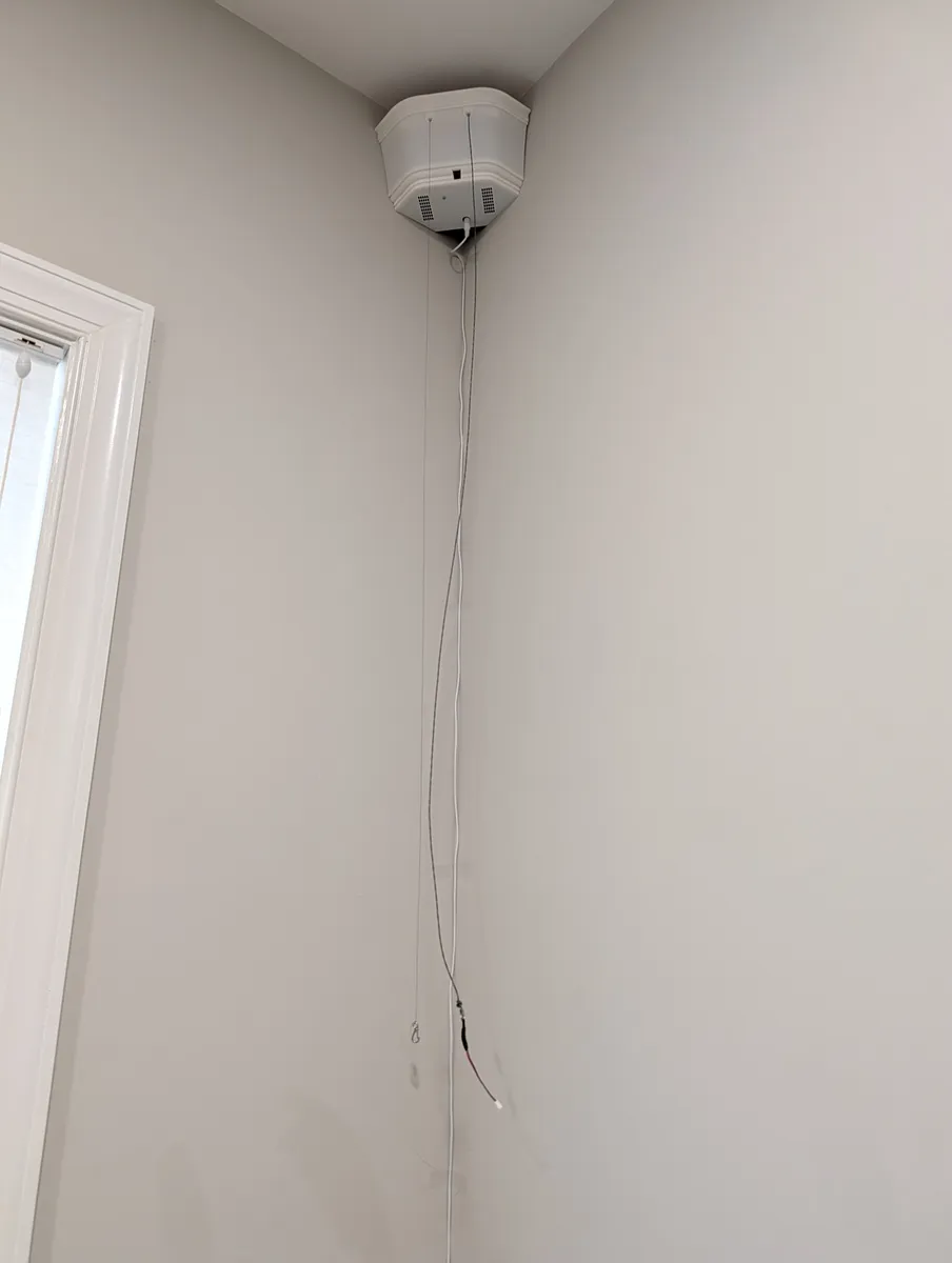
Repeat with the other anchor in the opposite corner.
Mounting Eyelets
In the two remaining corners of the room, With a single wood screw, screw an eyelet into a stud with the small pointer pointing up. It should be on the right wall when facing the corner, unless this corner of the work area is flat, then you just mount it however you can manage, as long as it's in a stud.
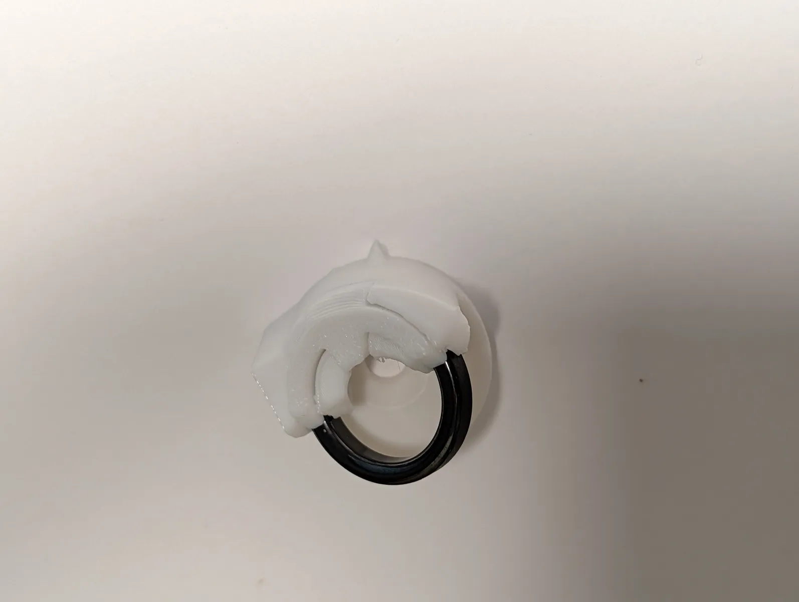
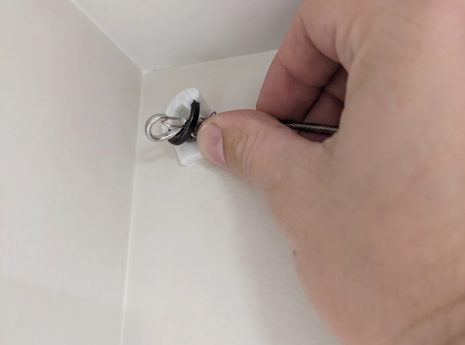
When facing the eyelet, look to anchor to your right. Take the carabiner from it's left line and pull it to you, put it through the eyelet from back to front, then pull it down to a level you can reach without a ladder.
Don't overtighten countersunk screws
Before Oct 2026, eyelets had a countersunk screw (cone shaped head). If you have this type, do not overtighten the eyelet screw of it can split the eyelet in half. Tighten only enough that the structure feels rigidly attached to the wall.
Mounting the parking hook
The parking hook is a place where the marker box and gripper can hang when the robot is powered off. It can be placed on any wall that is reachable in the robot's work area.
- The height of the parking hook should be high enough that you can comfortable walk under the lines while the robot is parked, and no higher.
- if mounted too high, it becomes very difficult to park because precision gets exponentially worse near the ceiling.
- the parking hook should be mounted in a stud.
Self parking is still a work in progress
Self parking, or any motion near the ceiling, is extremely dependent on good calibration, and therefore is hard to get working reliably. Depening on the room, you may find it to work, or may not. For that reason, I reccomend manual parking for now. (move near the hook, grab the robot with one hand, power off the motors with the remote, and hang the robot on the hook.)
After selecting a suitable location, screw the parking hook to the stud in the wall with the prong facing upwards. Screws are meant to be angled slightly for tool clearance.
Other parking options
You can also disconnect the gripper from the lines using the cabiners and run the debug command "stow" to reel in all the lines until some tension is felt. Before doing this mark which hook was the power line hook so you can re-attach everythign the same way it was during calibration.
Pre-tie-up connection test
Before hanging up the gripper, connect all components to wifi and confirm everything is ready, because once you do hang it, you need to be able to promptly raise and park it.
Powered components search for a wifi QR share code with their camera
- Plug in the gripper to the grey power line.
- Plug the anchors into the outlet remote switches.
- Power on the system with the outlet remote.
- Show a WiFi share code to each component.
Within about 10 seconds of booting, stringman components begin looking for a wifi share QR code using their cameras.
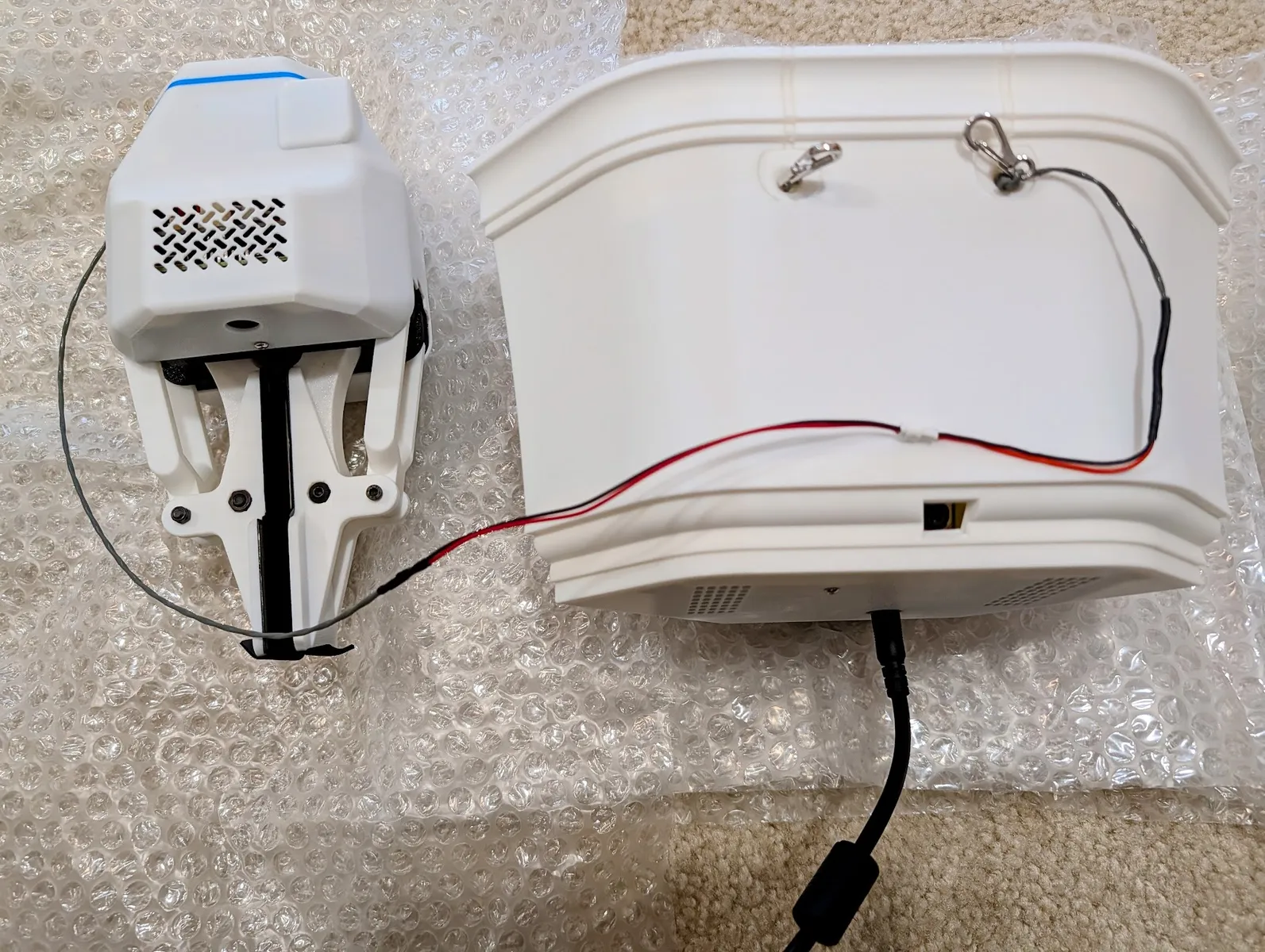
Always plug in barrel jack first
Anchors may be permanently damaged unless the barrel jack is plugged in before the AC power. Always plug in AC power (or turn on with outlet remote) last.
Only one complete stringman robot may be on the network during this step
In order for the controller to discover which components belong to this particula robot, If you own another stringman, turn it off.
Start up the Stringman controller on your computer. It begins searching for components on the network.
pip install "nf_robot[host]"
stringman-headless
Extra details on connecting to the network
Connect all components to wifi
Components search for a wifi network after booktng. If they cannot connect to a saved network within 10 seconds of booting, they look for a QR code in their camera.
To generate a QR share code, go to your phones wifi settings for the network you need to join and find the "share" section. This should show a QR code that is compatible with the standard. iPhone codes work fine, but android codes are decorative and only work if you hold them extremely close to the camera so they fill the whole frame.
For a more traditional blocky code that works well at a distance, Go to qifi.org on your phone and enter your wifi SSID and password. It will not be saved or sent anywhere. Press Generate to create a QR code.
Hold the QR in view of each camera (including the gripper camera) for about 10 seconds each. For traditional blocky qr codes, it can see a 5 cm qr code from about 1.5 m away.
When the component succsessuflly connects, it will buzz its motor or wiggle fingers to indicate success. You can also see it discovered in the stringman control panel. You can also see it show up in your router's admin page. For anchors, once connected, they start holding position as well.
Confirm that the control panel has discovered two anchors and one gripper. If it has not, power everythinng off and trying repeating the process.
If this method is not working for you, wifi credentials can also be added to the SD cards with the add_wifi_config.sh script.
If you have connection issues at this step, your anchors and host machine might not be on the same network. Guest networks won't work because they don't allow devices to be discovered by eachother. Please refer to the Troubleshooting Page or contact me on Discord to resolve the issue before tie up.
Wifi creds can be cleared from a gripper by rapidly squeezing the finger pad five times.
Firmware update and timezone sync
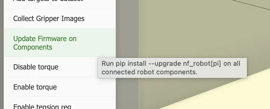
With all components connected to the motion controller, select "Calibration and Maintenence" > "Update Firmware On Components" from the run menu. Wait for confirmation of completion from all components. Updates are not pushed automatically, they are always done at your discretion.
Tie up
You've got it connected, time to tie it up properly. Power off the whole system during this step.
Place the gripper in the center of the room. Pull out each of the four lines to the center. Black carabiners from anchors should attach to the black bar. Silver carabiners from eyelets should attach to the white corners of the marker. This way the anchors are always looking at the marker face on. No lines should cross.
Plug in the power to the gripper from the end of the gray line if not already plugged in.
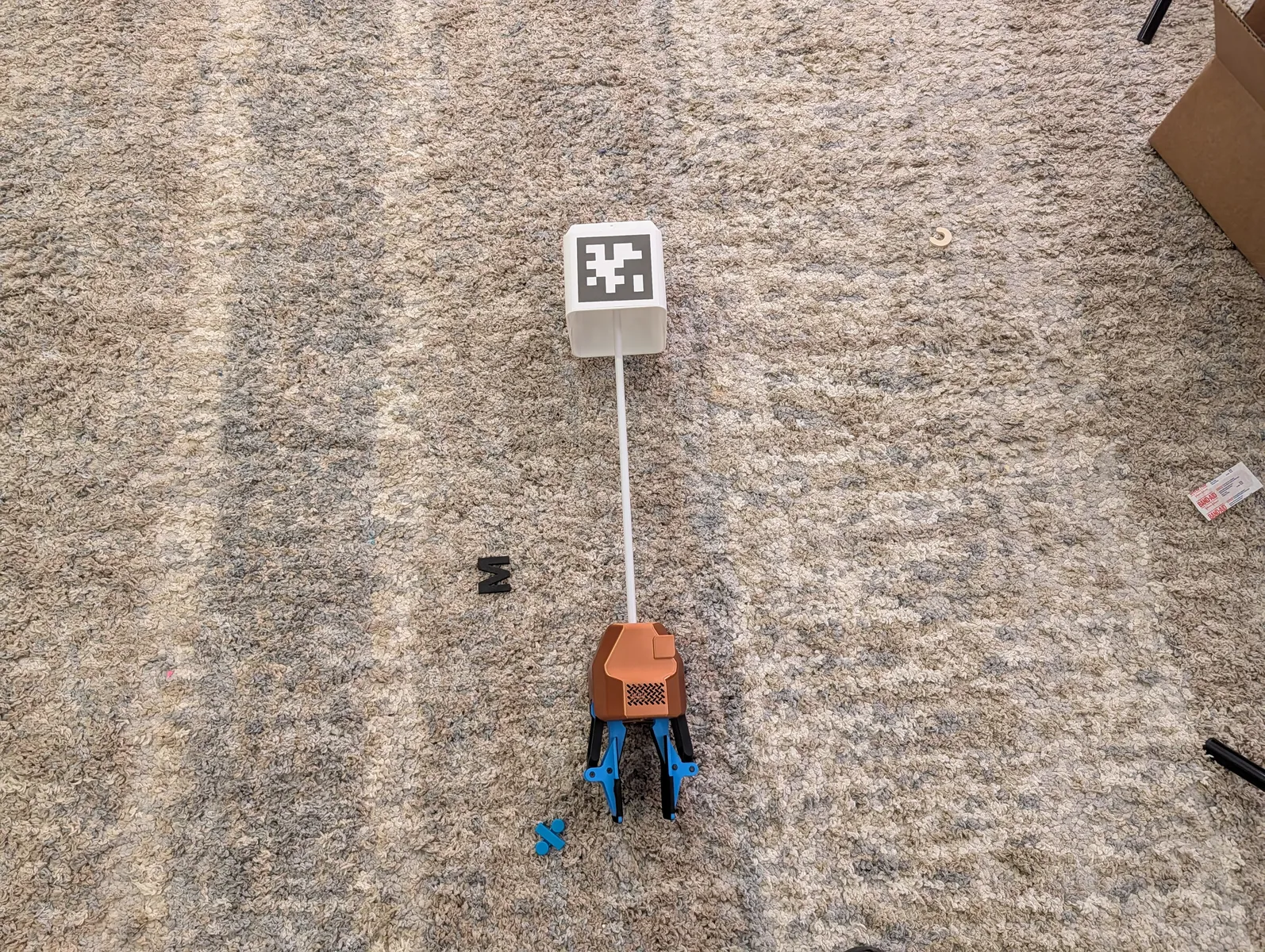
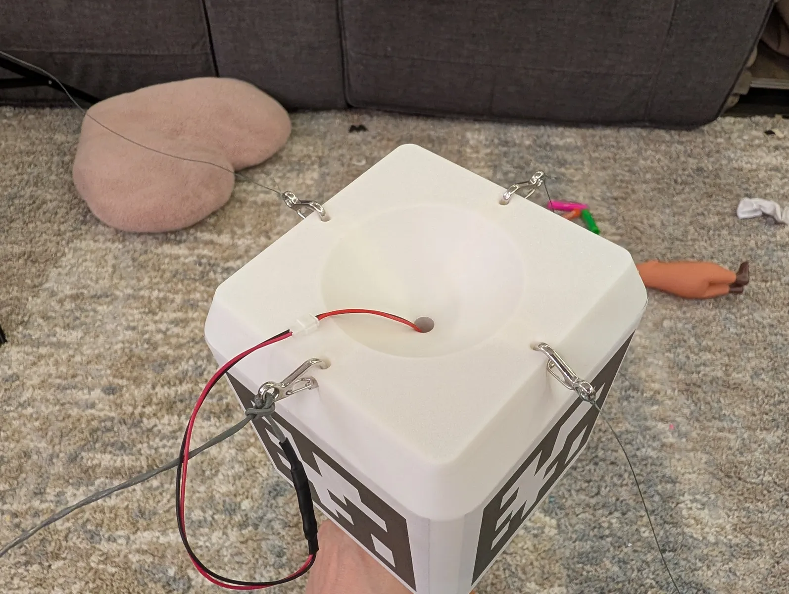
Power the system back on.
In the control panel wait for all components to be discovered. Select "Tension Lines (D-Left)". this should tighten all four lines. 2 on the keyboard is another shortcut for this. Hold E for a second or two to move up off the ground. More complex motion requires full calibration.
Full Calibration
Prepare for calibration by placing the four large paper cards on the floor. The one labelled "origin" should be in the center, with the others around it anywhere. At least one should be on the floor. The small plastic cards are not part of calibration, they are for labelling drop points during normal operation.
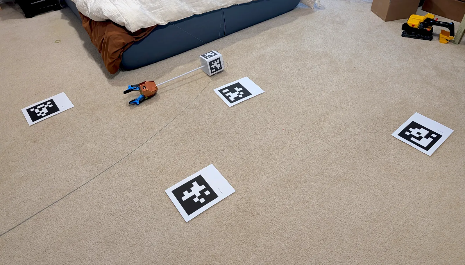
With the gripper near the center of the room, touching the floor, select "Calibration and Maintenence" > "Full Calibration" from the run menu. It is normal for some lines to be slack during calibration, this is a necessary step to determine the location of the eyelets.
If a card moves, stop calibration and start again.
If any card moves during calibration, the abort it by pressing STOP and start again.
When calibration is complete, you will see a message in the UI. You can judge the quality by checking that the room shape in the UI matches the work area of the components you installed. Moving in straight lines with WASD should result in staight line movement of the robot. Secondly you can enable swing cancellation and confirm it cancels the swing rather than amplifying it.
A lateral move forwards (W or up on the left stick) should move in the direction the gripper's nose is facing when controlling from gripper perspective (the default). If this does not occur, try repeating calibration.
If calibration results are poor, trying moving the calibration cards further apart and try agian starting with the gripper on the floor near the center of the room.
Changing the camera tilt angle
Different room shapes and ceiling heights may require tilting the camera up or down. If you find that there is too little overlap of the two cameras on the floor for you to place several cards in view of both, you may need to adjust the camera tilt.
Remove the anchor cover. Press either the top or bottom edge of the camera tilt mechanism to adjust it by one click at a time. Check for better overlap in the composite image by either re-running calibration (slow) or directly inputting the known angle into the component context menu.
Calibration automatically discovers the true angle of the camera.