Arpeggio Anchor Build Guide
Hardware Version: Arpeggio
Print time: 40h
Build time: 1.5h
Resources
Tool list
- Mini screwdriver with a bit set. Manual or Electric
- Cross locking tweezers
- Super glue (loctite super glue “professional liquid” recommended)
Soldering
Kits purchased from neufangled.com after Jun 26 2026 do no require any soldering. Kits earlier than that, or parts sourced yourself may require soldering.
Spools
A full system needs three regular having fishing line, referred to below as "regular" spools and one power spool which has cable wound on it. Spool side A is different on the powerline spool, it has a wider center hole.
Glue side A to side B
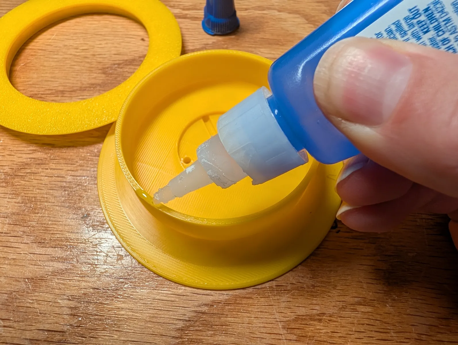
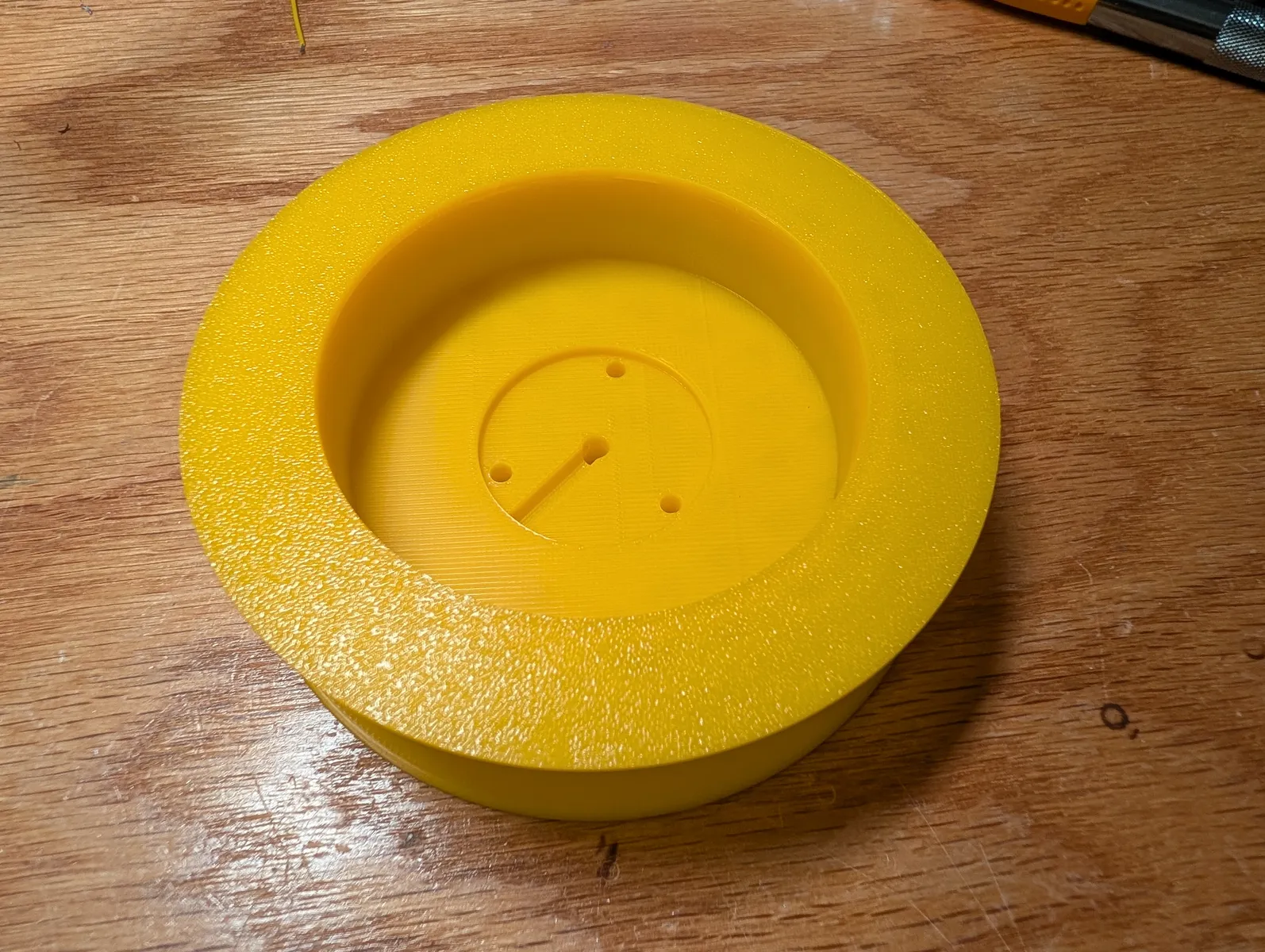
Regular spools (create 3 per system)
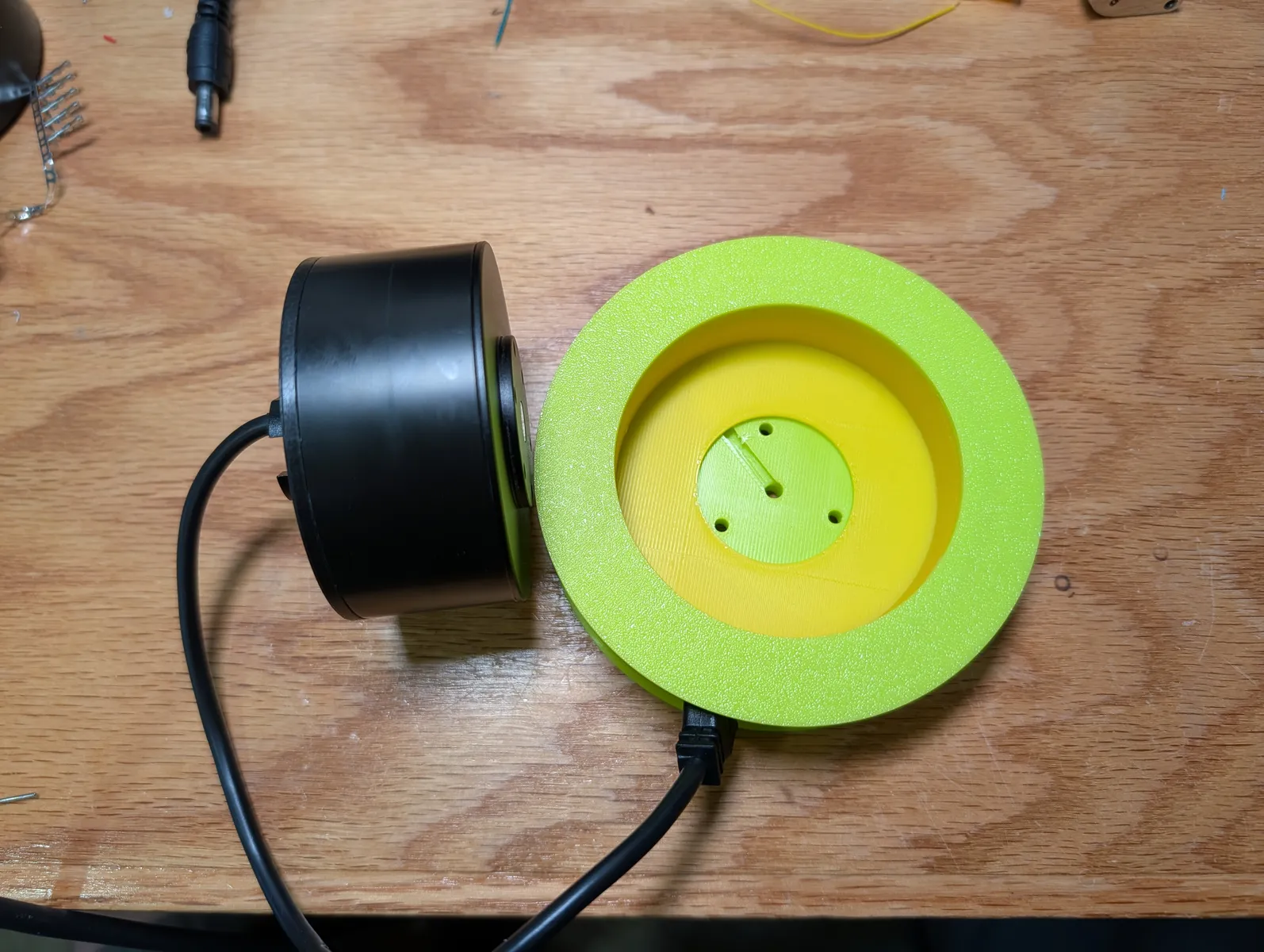
Press the dry spool onto the motor until fully seated. twist until the holes align, secure with 3 M3x8 screws.


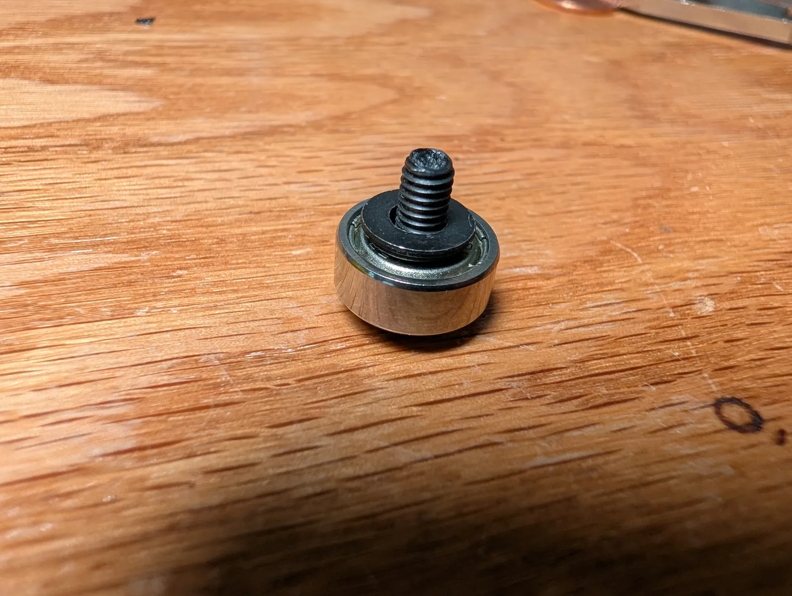
Put an M4x12 screw through a 4x13x5 bearing follow by 2 M4 washers, then screw it into the 4 mm hole in the center of the spool with a dab of superglue or loctite.
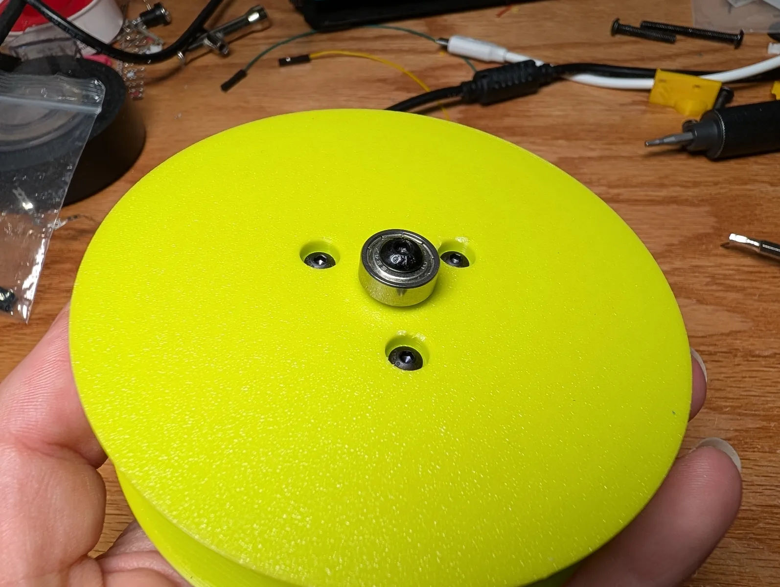
Powerline spools (create 1 per system)
Solder a JST ZH female plug housing onto the fixed end of the slip ring.
Glue the 1cm abs tube (included in the kit) into the hole in the powerline spool side A. You can use a coin to press it in.
Creating the 1cm tube
Use an "imp" pipe cutter to cut an 10 mm long peice of 10 mm diameter ABS tube. The same tube used on the marker box of the arp gripper.

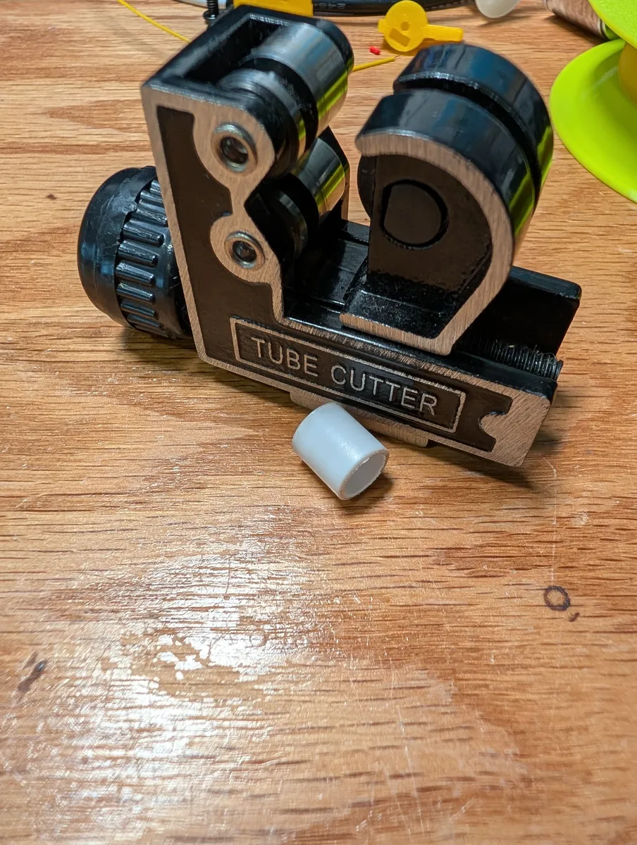
When dry, put 3/8 * 7/8 stainless steel washer on the plastic tube, followed by a 10x15x4 bearing.


Place the slip ring into the slip ring block and secure it using 2 M3x8 screws with an m4 washer on each in the 2 out of 3 accessible screw holes.
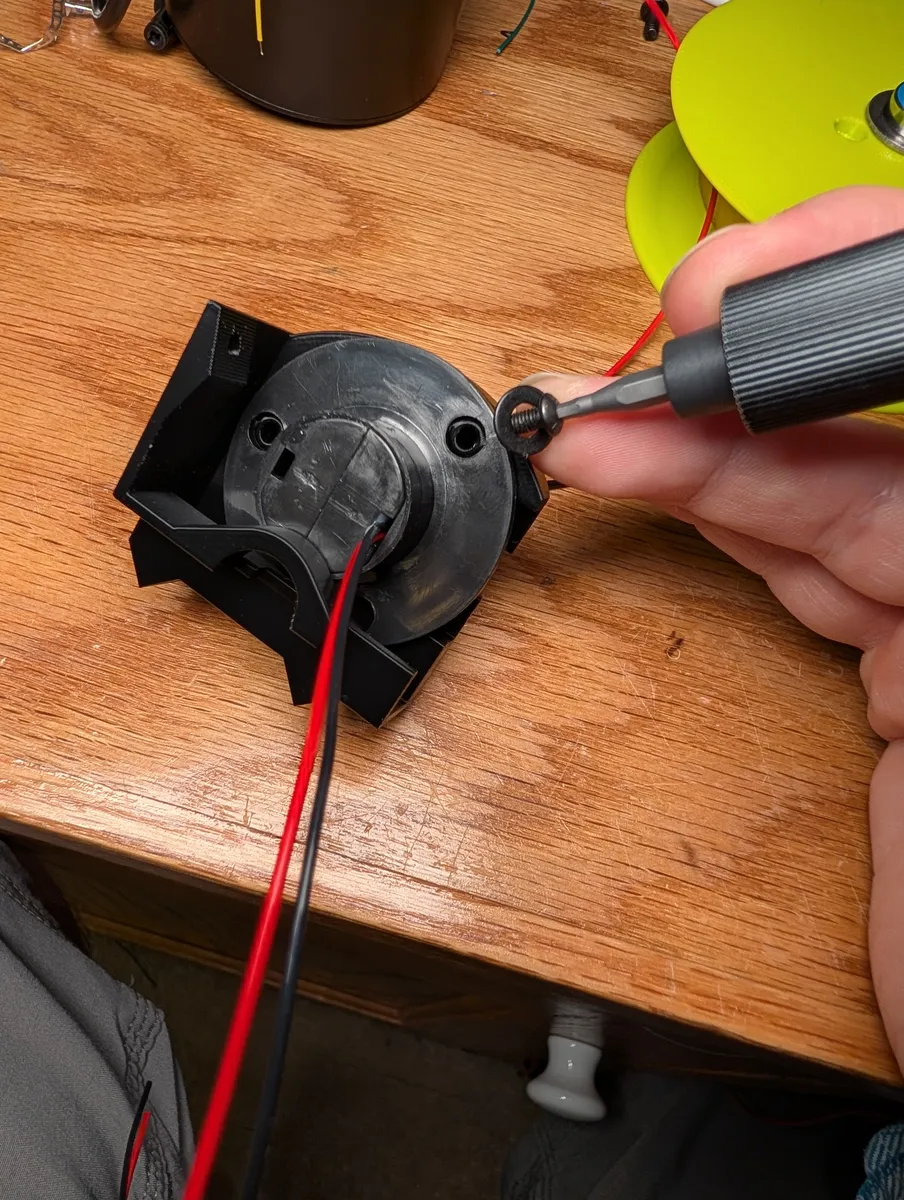
Thread the rotating wire end through the tube in the spool about half way, and using the access you still have to the back of the spool, thread the wire out the side of the spool through the wire hole. don't sinch it all the way down yet in order to leave room for the screws that secure the motor.


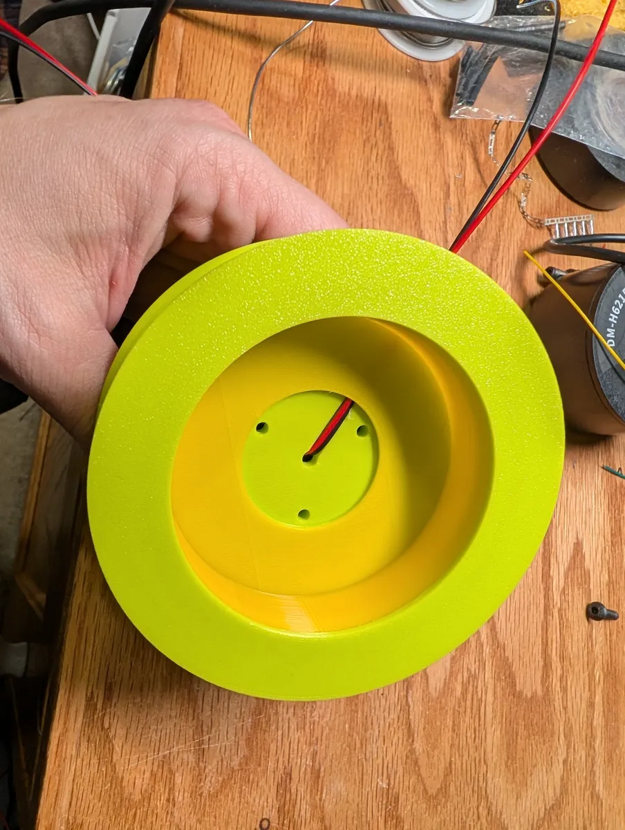
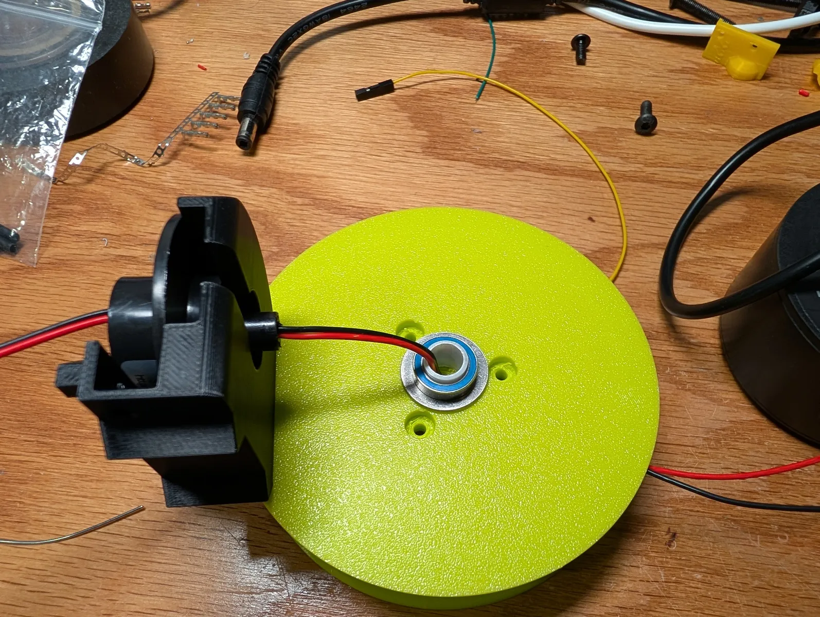
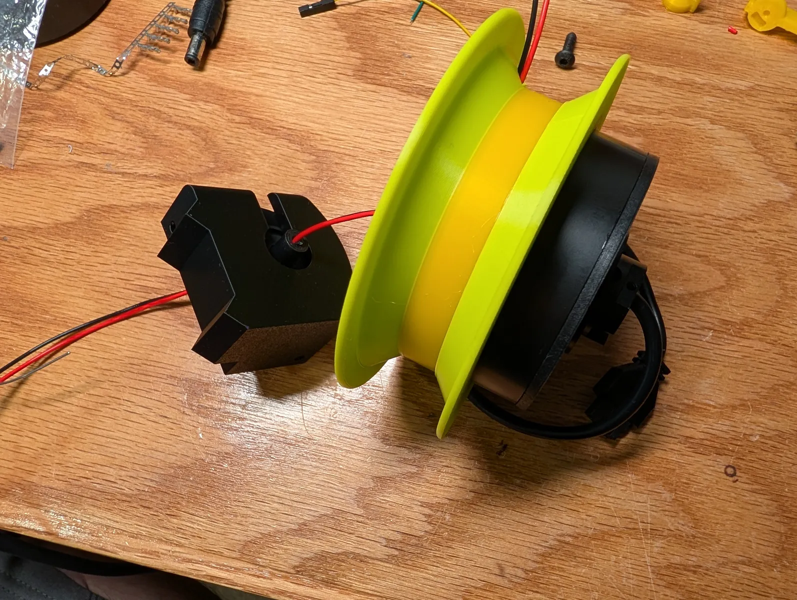
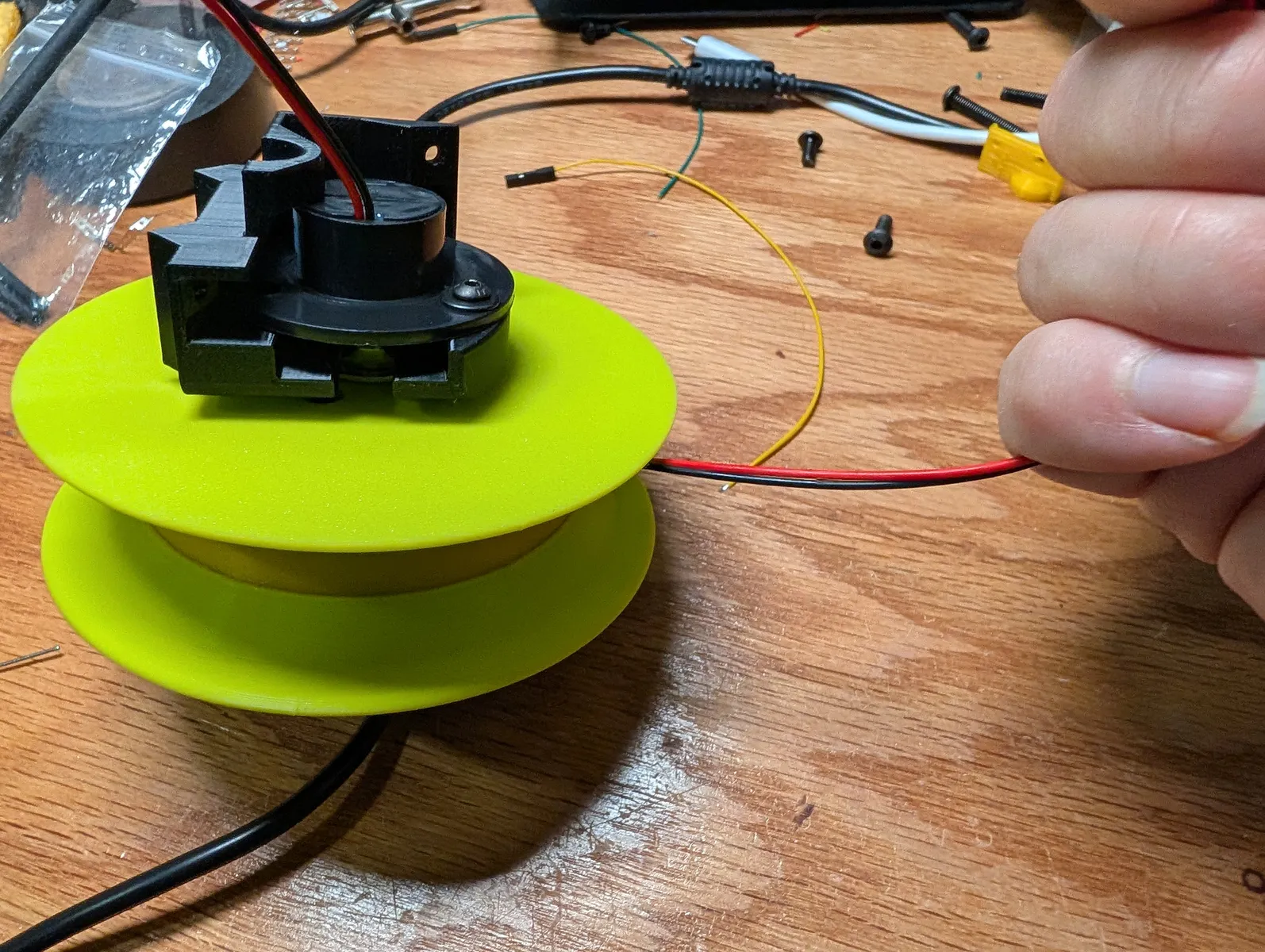
Press the motor into the spool, align the holes and secure with 3 M3x8 screws. Now fully seat the slip ring against the side of the spool by gently pulling the wires through.


Electronics
Assemble a Raspberry Pi 3A+ with a Stringman imaged SD card and single heat sink on the broadcom chip. Note that the 3A+ image is different from the Zero2W image.
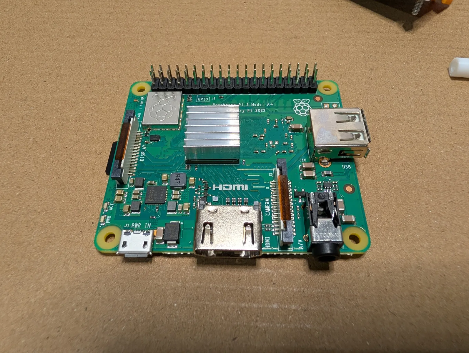
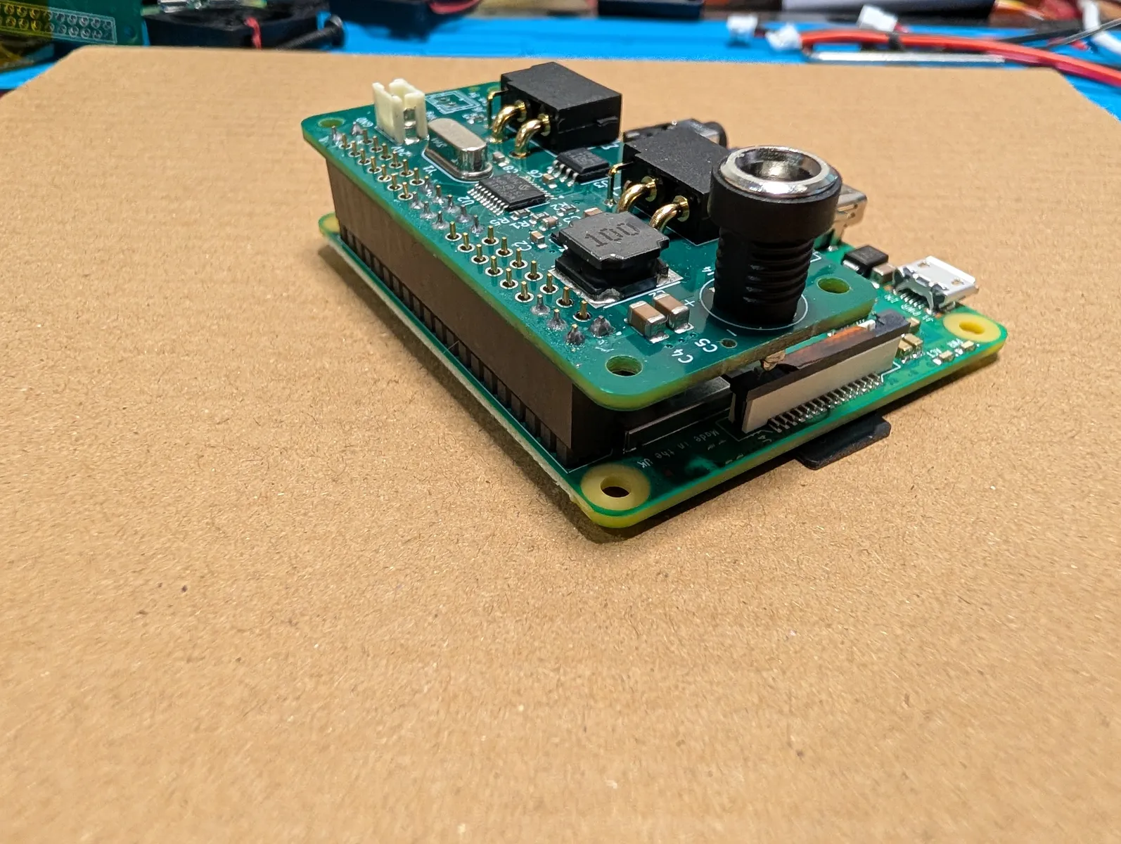
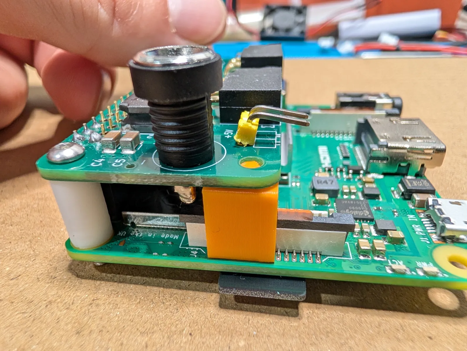
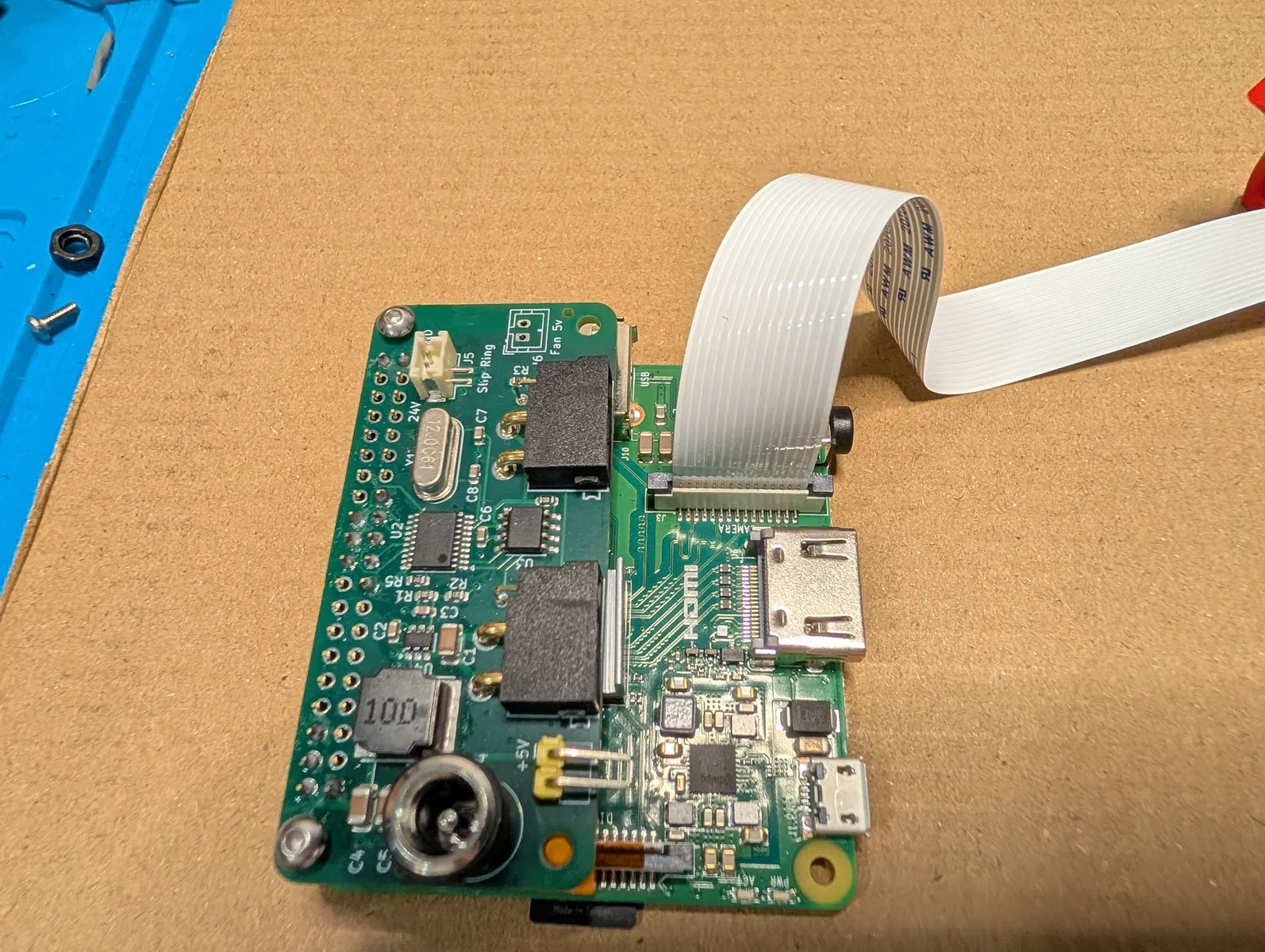
Press a Stringman Anchor Hat onto the pi. Put cylindrical spacers in the corners between the two boards and insert two M2.5x18 screws in the holes at the corners, through the hat, spacers, and pi.
Under the barrel jack, wedge an "odd spacer 2". the part looks like a single peg lego piece and supports the barrel jack so it can't bend the hat down when you push a plug into it.
Camera sub-assembly.
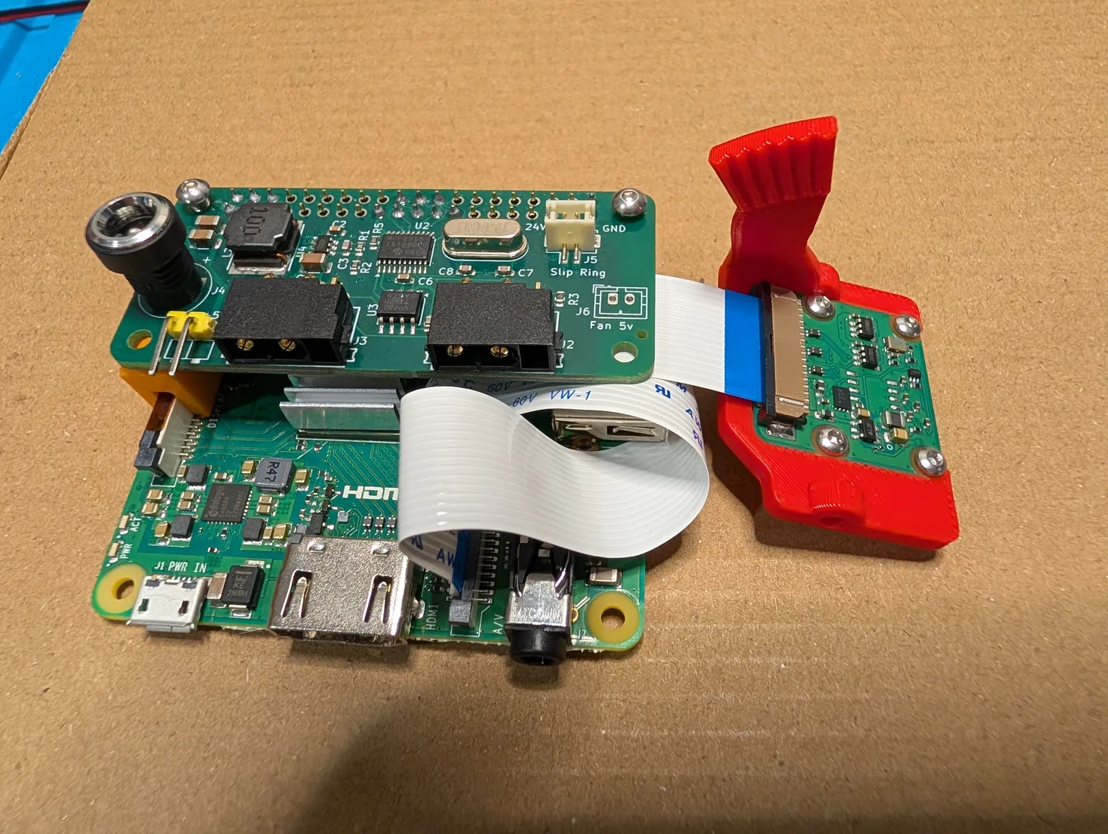
Carefully unpack the a Camera Module 3 standard FOV. Leave the white (full size) ribbon cable attached.
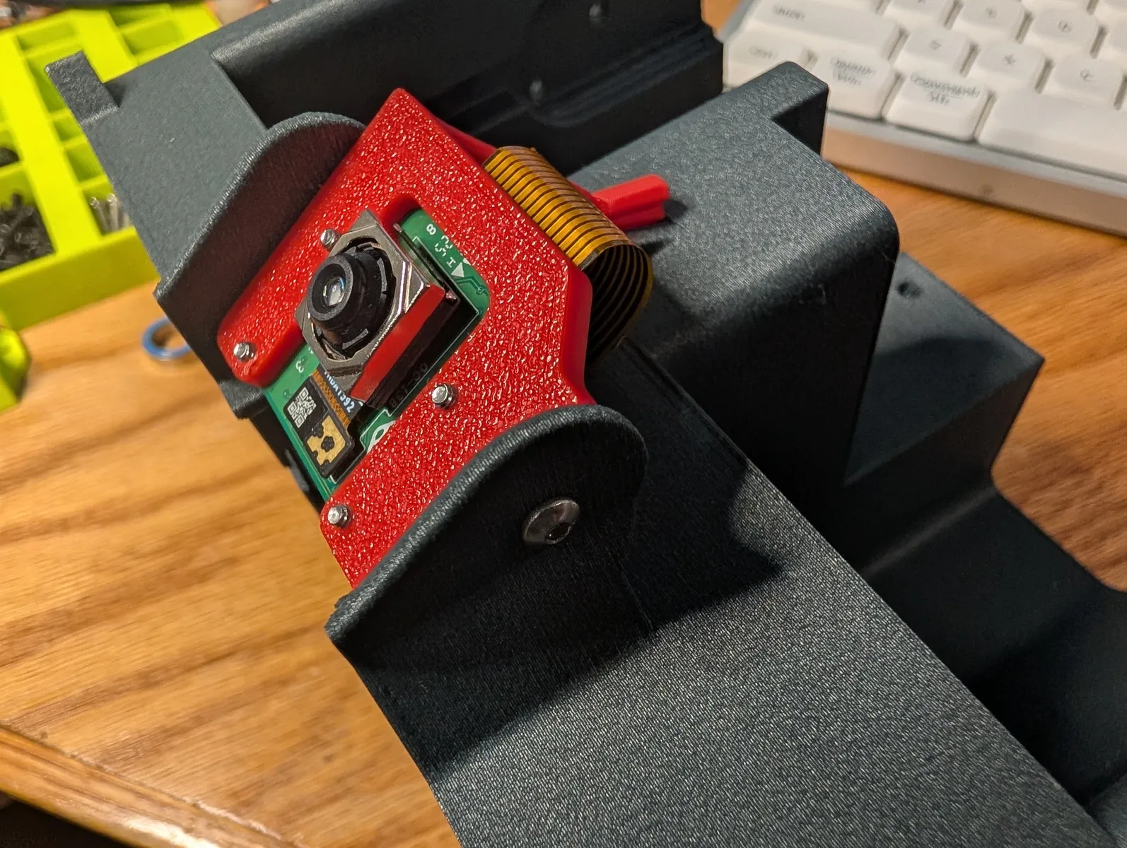
With the camera face down on something soft to protect it's autofocus mechanism, screw it into the adjustable tilt adapter as shown using M2x4 screws on all four corners.
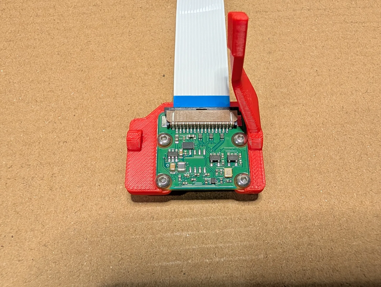
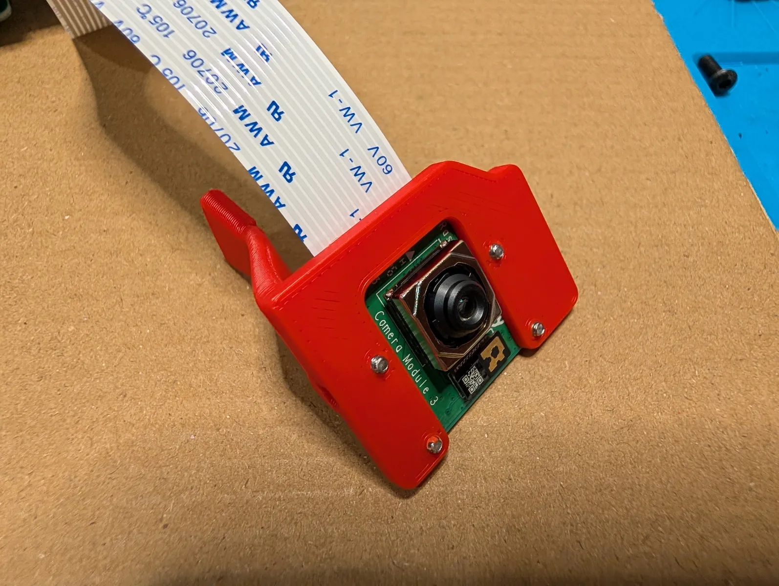
Insert the other end of the ribbon cable into the rasberry pi zero 2w 's camera ribbon connector (the one near the center of the board) as pictured. The ribbon cable has excess length, so tuck an extra fold of it under the hat.
Install Pi into anchor frame.
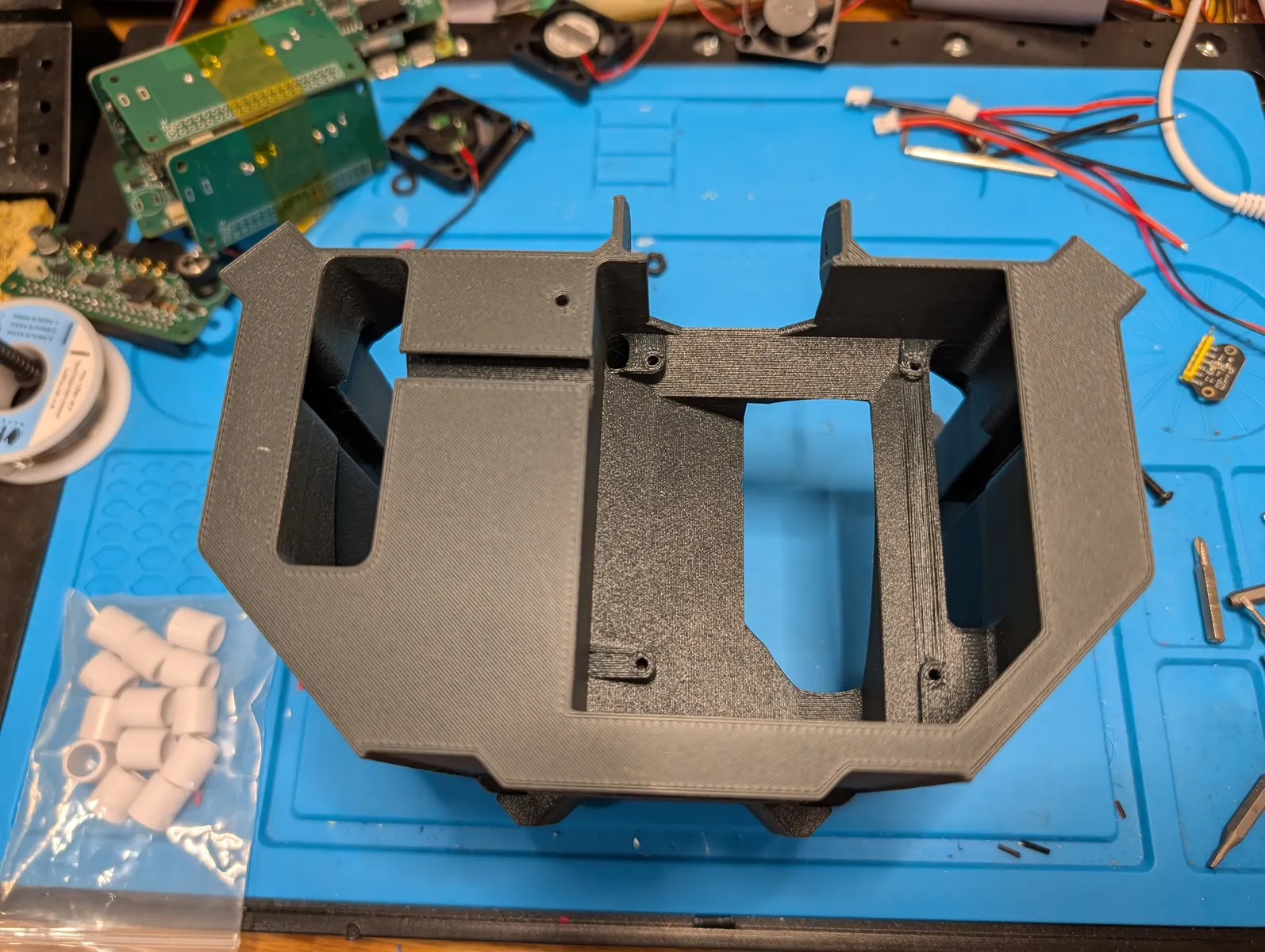
Screw the raspberry pi into the electronics box on the bottom of the frame. First using the two M2.5x18 screws, followed by two M2.5x6 screws in the remaining holes. The camera should hang out of the window at the front
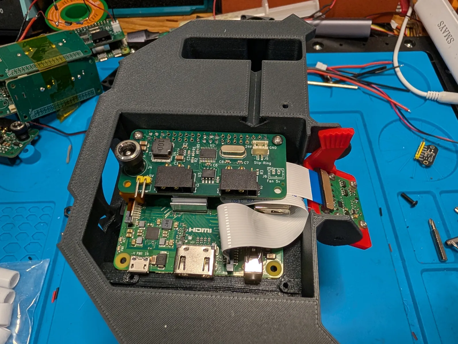
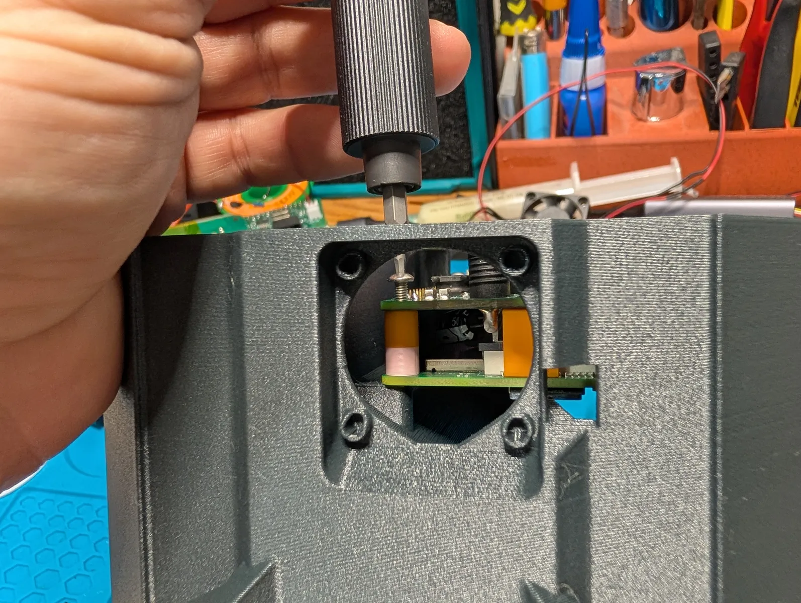
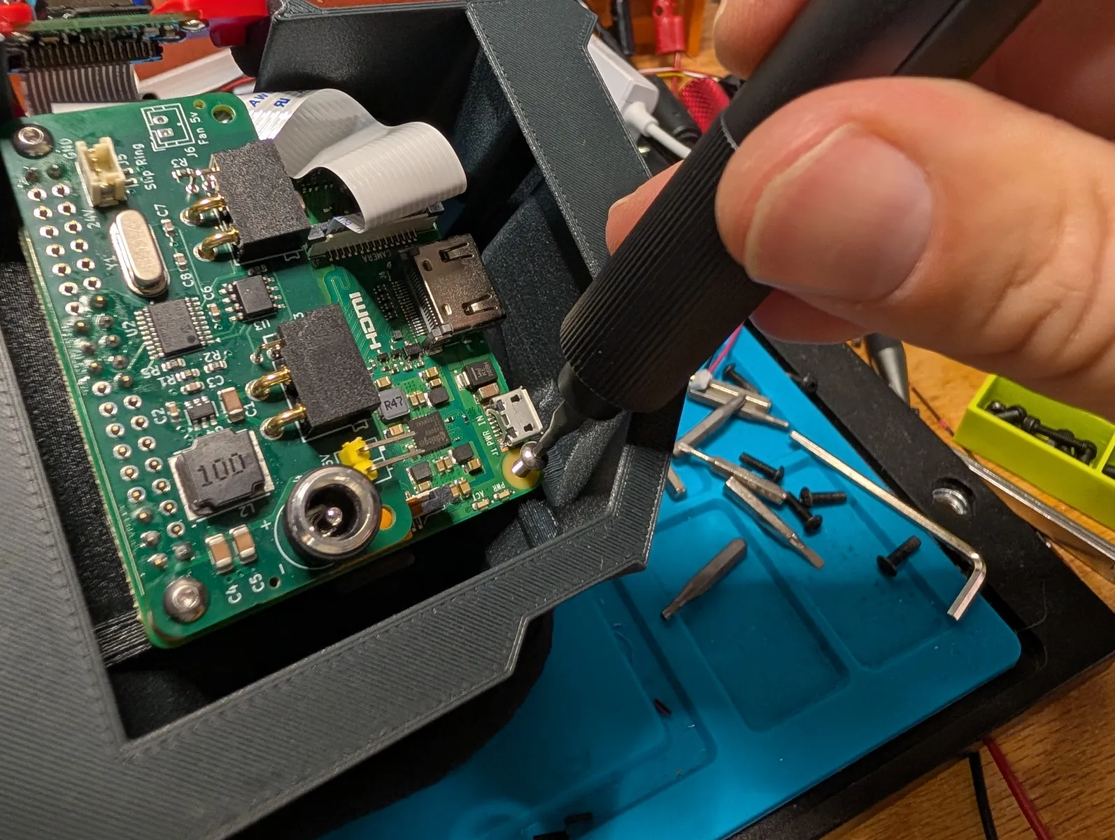
flip the camera over and wedge it between the two protrusions on the frame. Insert the toothed arm into the corresponding slot on the frame. Take care to align the screw holes on each side and screw two M2.5x6 screws into the the sides of the adapter, securing it to the frame
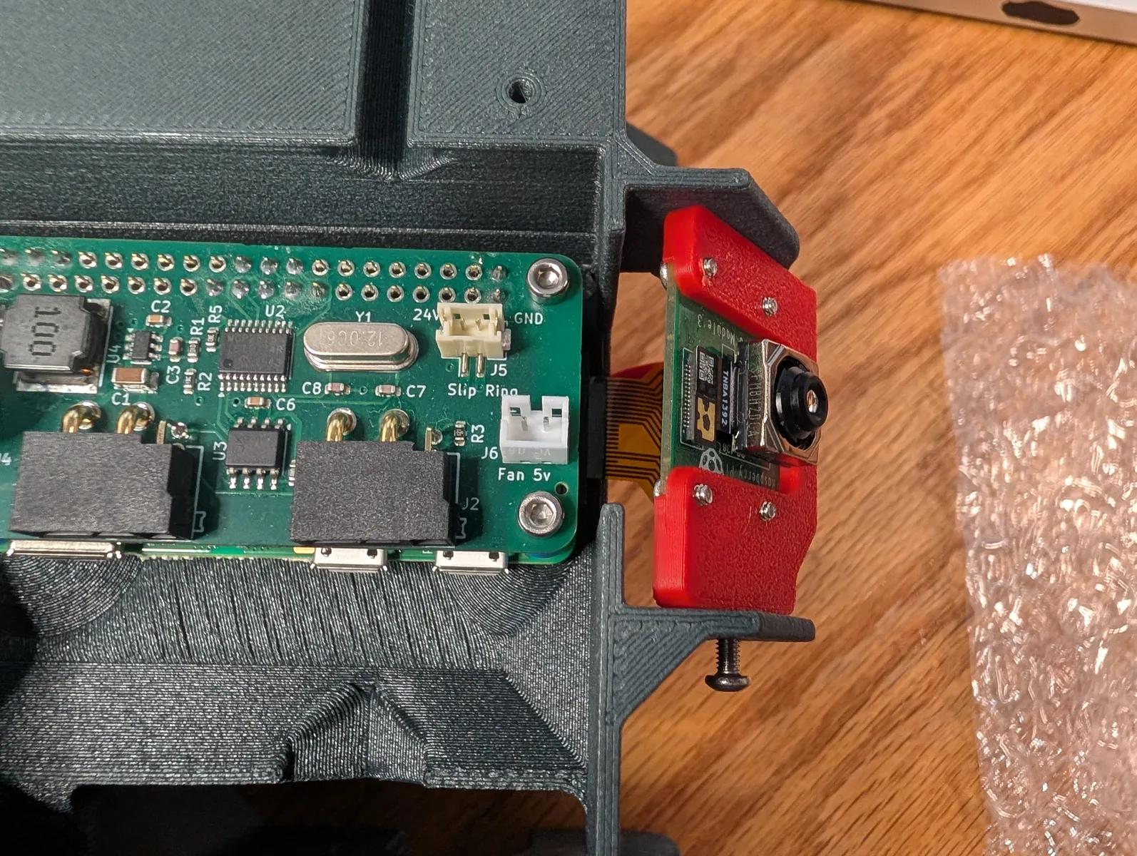
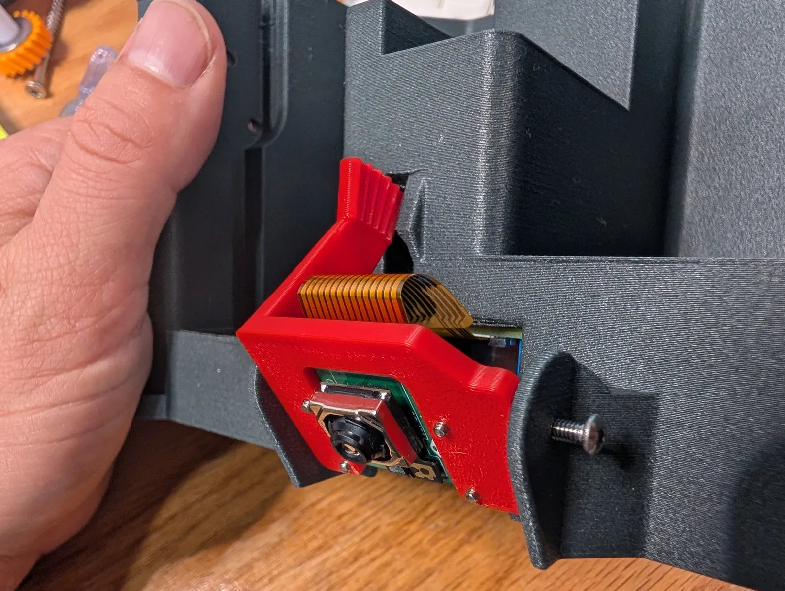
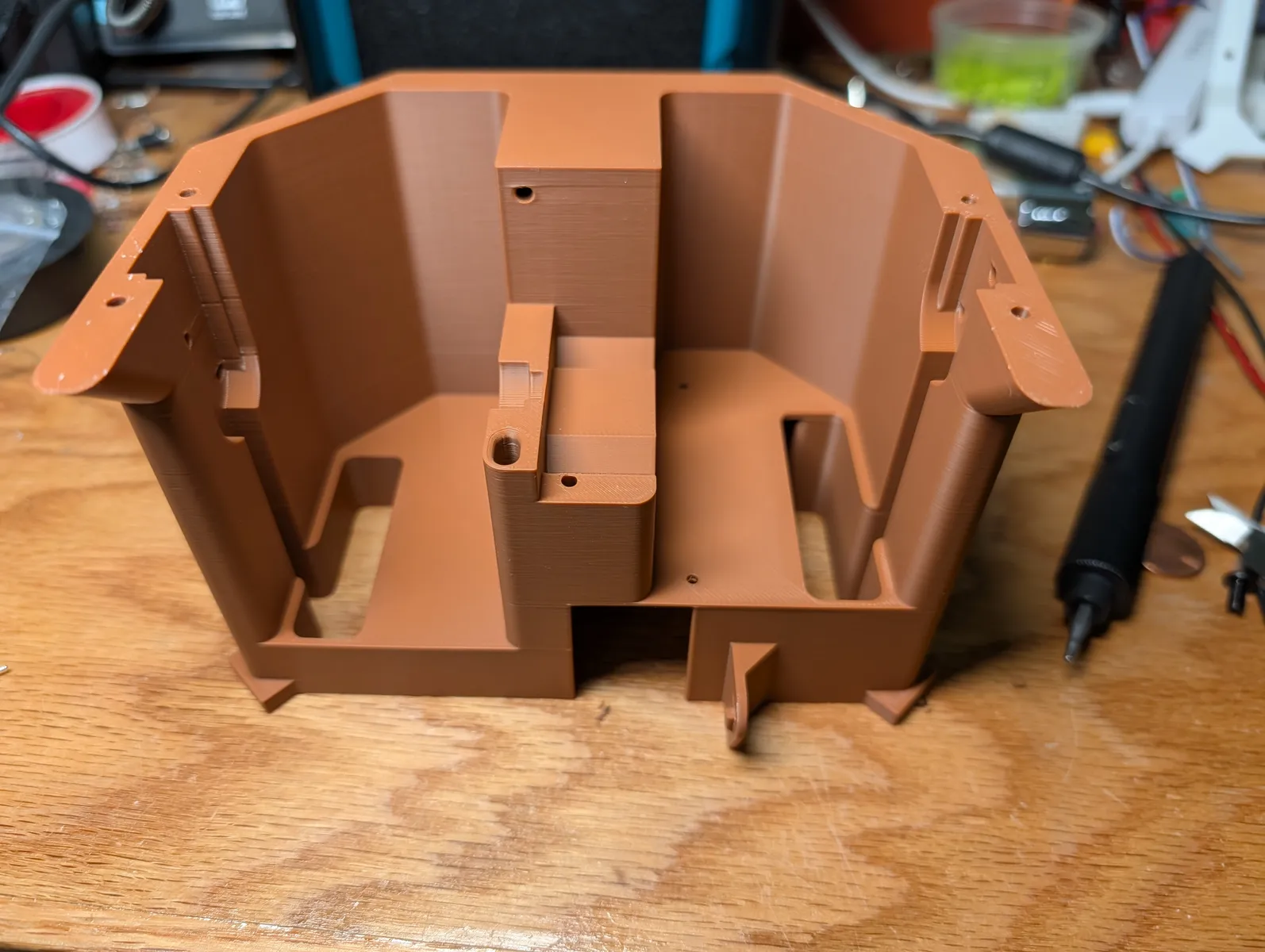
Frame
Flip the frame right side up. From this point on it can be very helpful to have a beanbag to place the mechanism on at any angle while driving screws.
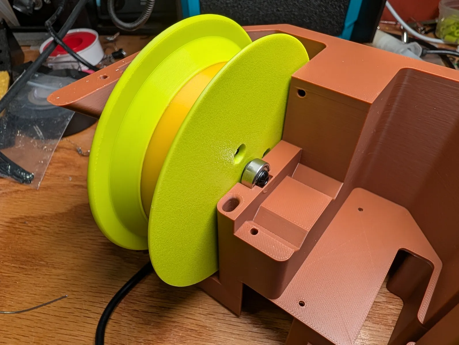
Install the lower spool first. Insert the plug downwards through the rectangular hole on the lower spool side of the frame. Align the motor's shaft so the gap points down and the flat sides are vertical. slide it into the slot, pulling the wire through as you go. seat it fimly in the slot, and in the bearing cup on the other side. spin and confirm it's not crooked. Secure the motor from the outside of the frame with 3 M3x8 screws.

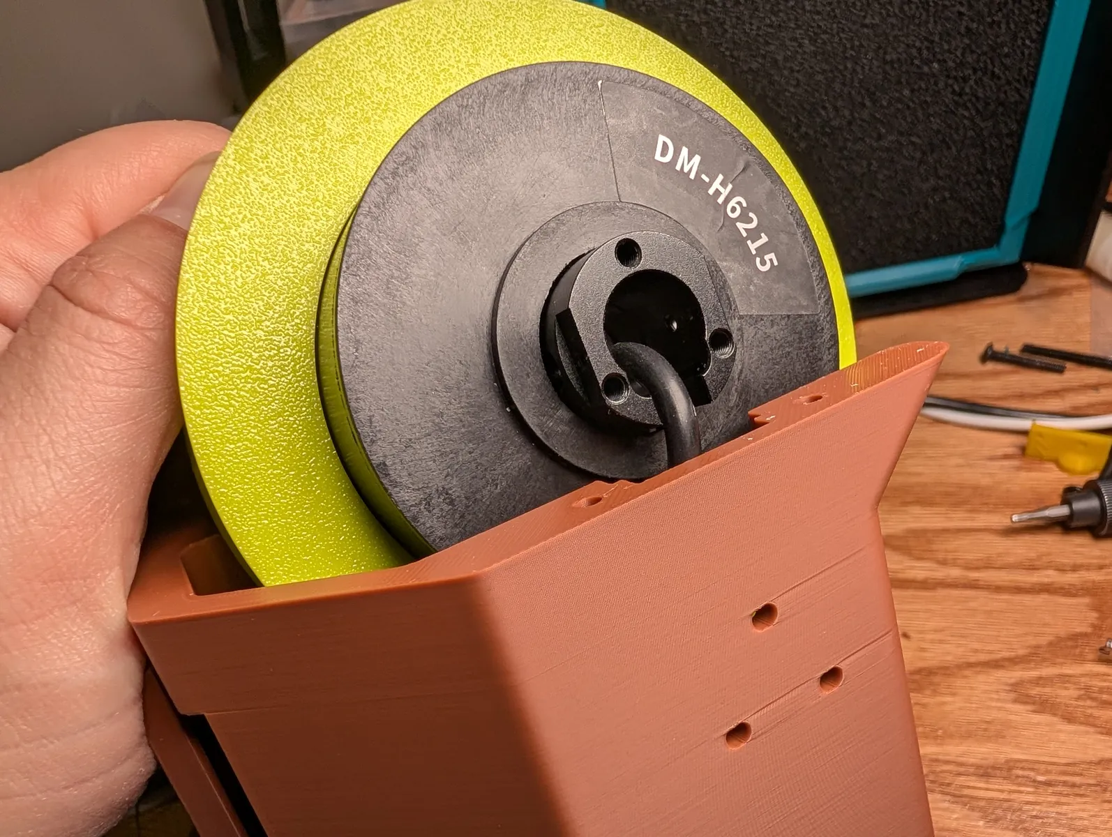
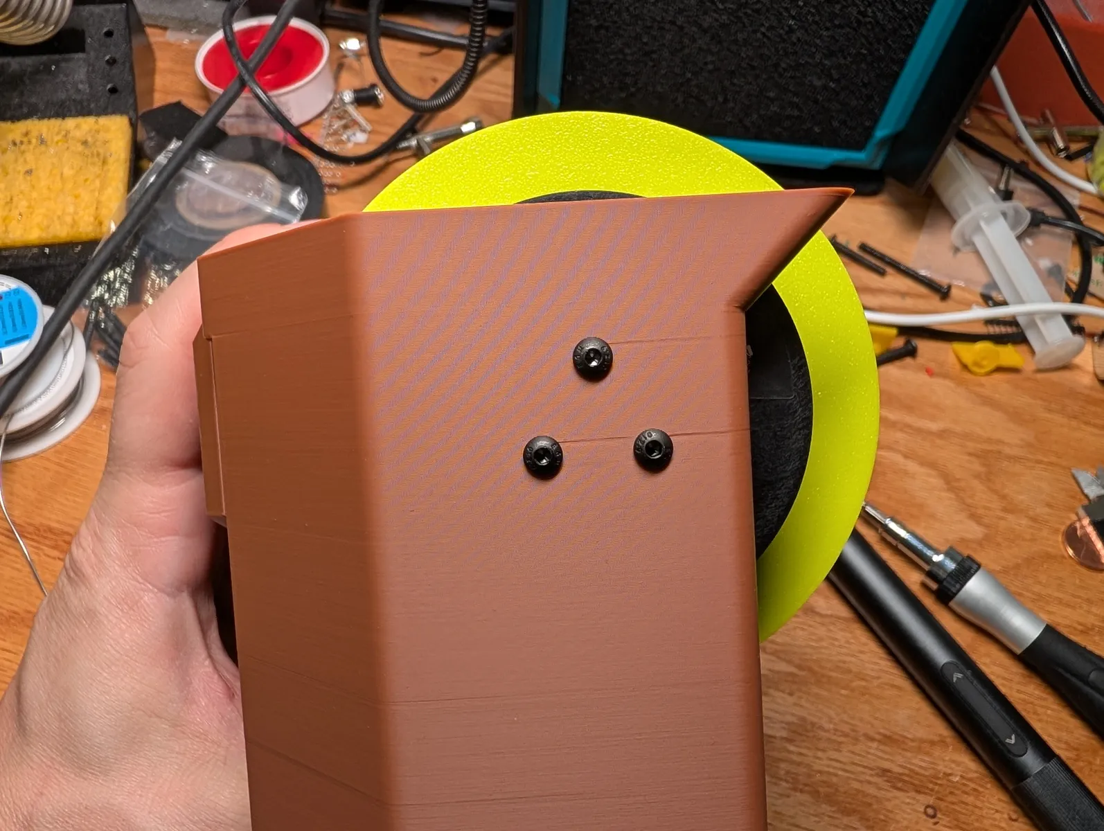
Avoid cross threading the motor screws
first rotate backwards to ensure you are engaged with the metal and not just plastic.
If the higher spool is a regular spool, print the variant of the slip ring block made for regular spools instead of slip rings. press it onto the bearing that protrudes from the unmounted spool.
If the higher spool is the powerline spool, it already has a bearing block on it. sinch the wire down firmly by pulling it through the spool till the slip ring cannot get any closer to the spool.
Same as the other one, thread the plug, align the shaft, and align the bearing block on the other side. secure the motor with with 3 M3x8 screws from the outside of the frame, and secure the bearing block with two M3x8 screws.
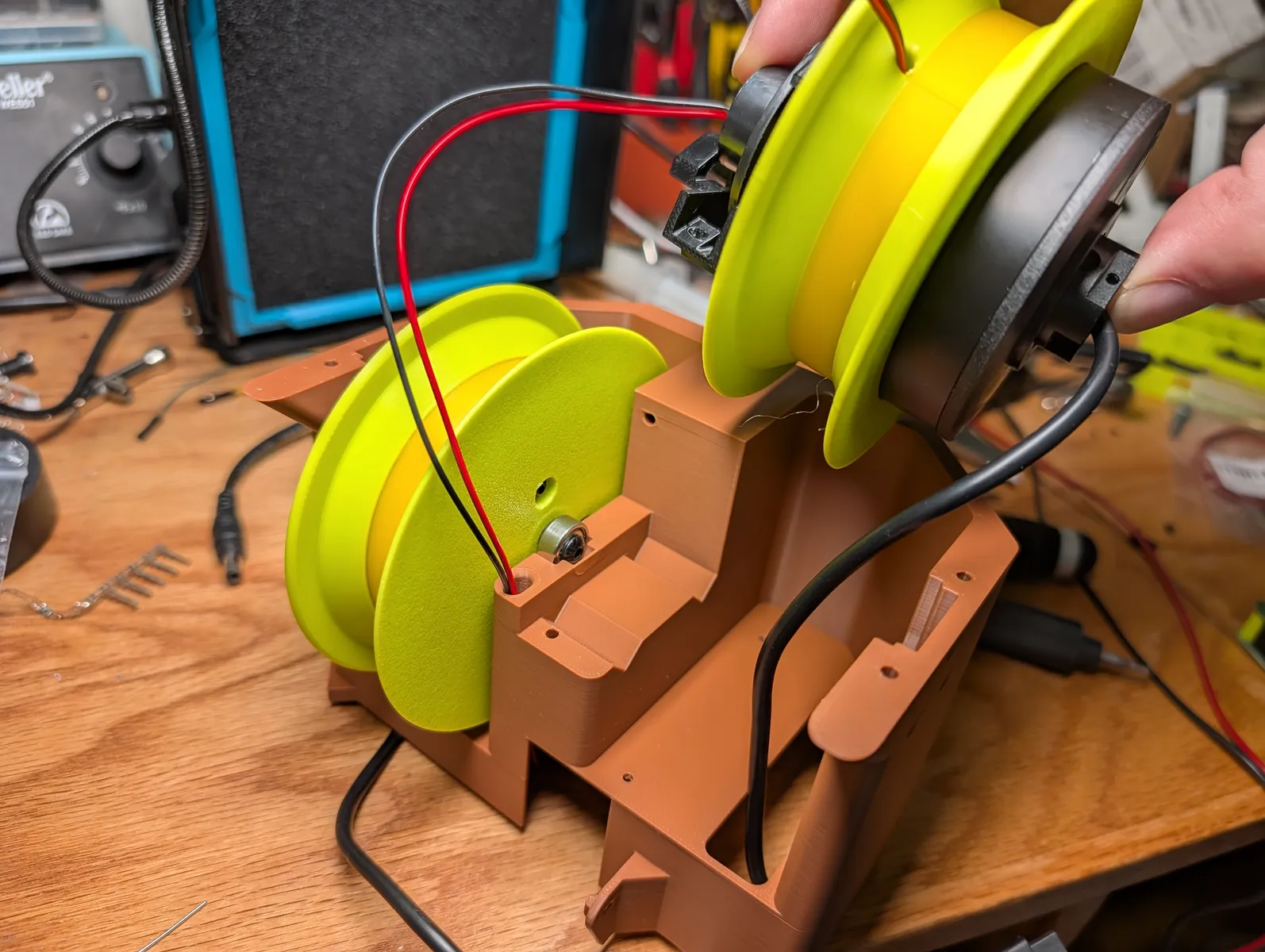

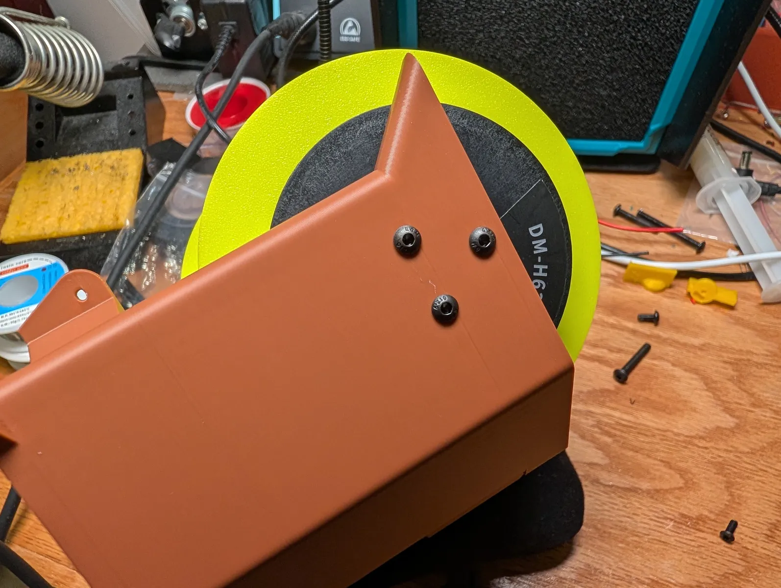
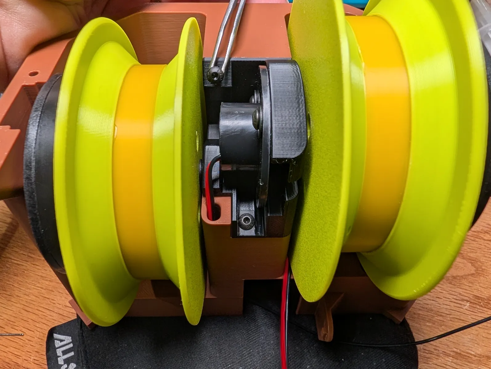

Secure the "sunglasses" to the top of the frame with 4 M3x8 screws.
Spool winding
Winding is performed by running a post-assembly script on the anchor (qa-anchor-arp) It sets motor ids, winds the correct amount of line for the spool type, and checks the camera.
This video summarizes the process for a non powerline anchor
Power on the anchor.

Begin by logging into the anchor. You can connect it to the internet either by wifi or ethernet using an adapter. Power on the device and ssh into it with
ssh pi@<hostname or ip>
Password Fo0bar!!. Then run
/opt/robot/env/bin/pip install --upgrade "nf_robot[pi]"
/opt/robot/env/bin/qa-anchor-arp
Follow the prompts. It will ask you to plug in one motor at a time and power cycle them which can be done by pulling and replugging the motor plugs from the hat (not the barrel jack).
If you lose your connection at this step, just log back in and run the script again, it will pick up where it left off.
Once motor ids are set, it prompts you to wind the spools. If you are not ready to wind a particular spool or need to skip it, answer no (n) at the prompt for that spool.
Fishing line spools
Before winding a fishing line (regular) spool, tie the end of the line to the small tie off point on the spool with a buntline hitch.
Hold the supply spool loosely in a clear place. Winding is pretty fast. Winding starts after answering yes (y) for a spool and pressing enter in the /opt/robot/env/bin/qa-anchor-arp script.
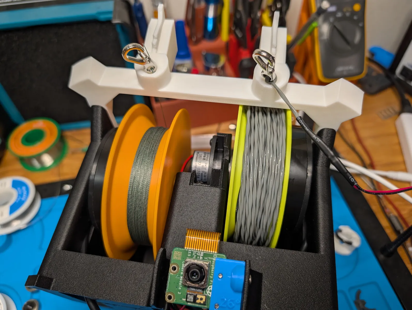
When winding is finished, feed the line end out of the sunglasses from back to front, then tie a carabiner on the end with a palomar knot. If you have both colors, tie silver on the left side, and black on the right side.
Power line spools
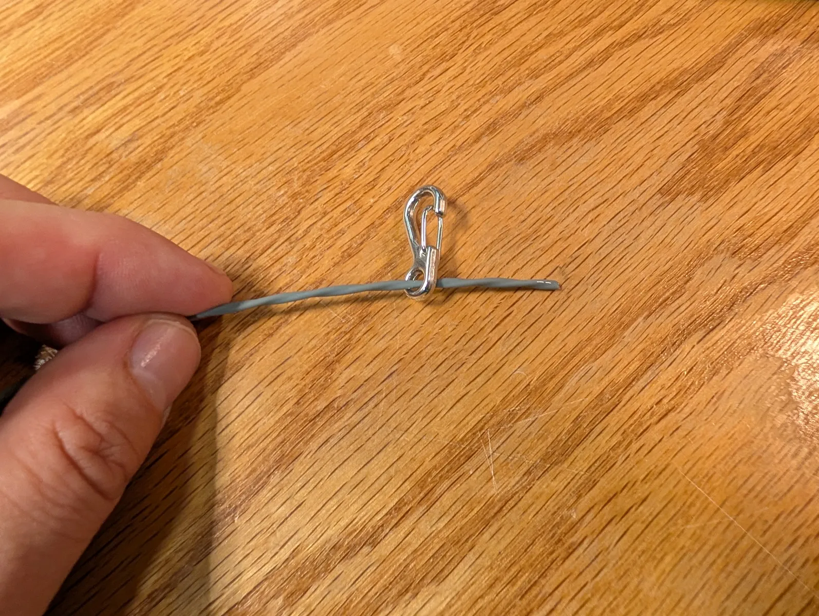
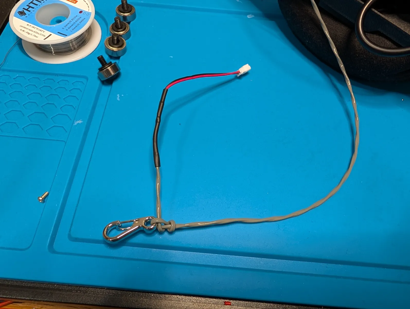
First, if you bought a kit and received a pre-cut length of cable, thread one carabiner onto the bare end of the cable now through the carabiner's small hole, and send it all the way to the other end where the JST plug is. We'll need it there later.

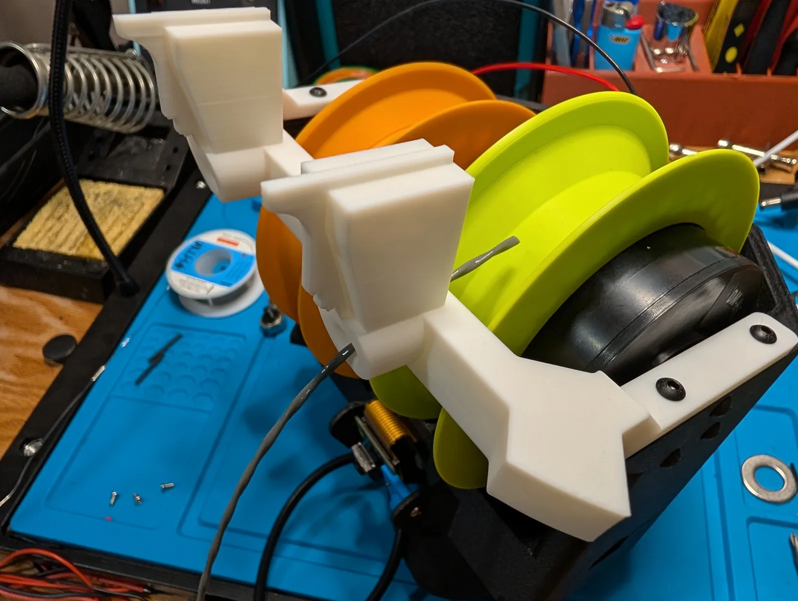
Next, feed the bare end of the cable into the front of the "sunglasses". Pull a lot of slack through, and then feed the cable through the spool's tie off hole in the other direction, from the back of the anchor to the front, as pictured.
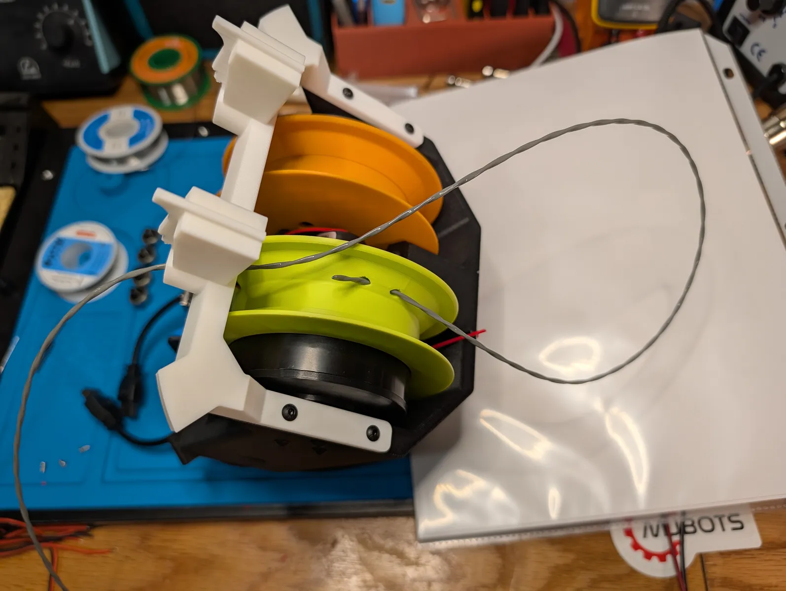
Pull more slack through the tie off hole and tie a simple square knot. Do not cinch it tight yet.
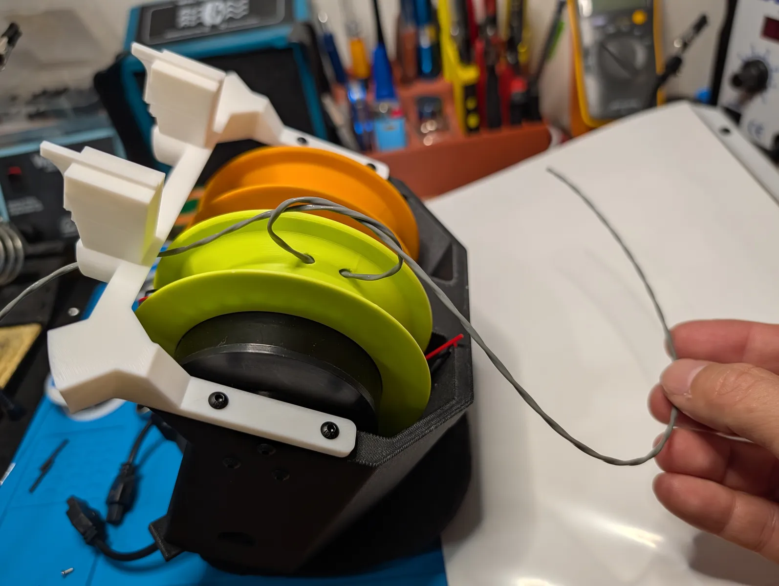
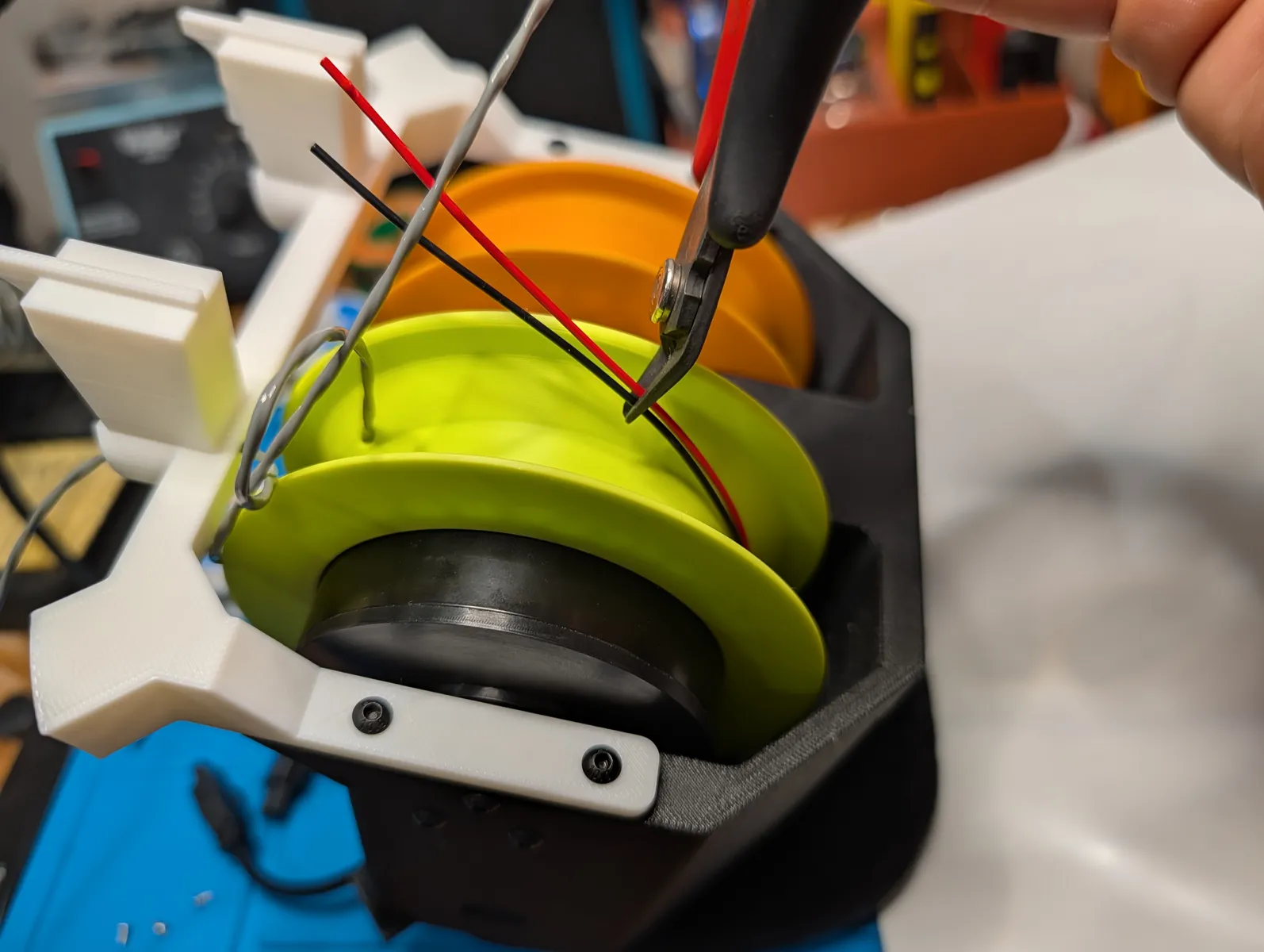
Rotate the spool forwards and trim the slip ring wires at the point pictured. this causes them to wrap about 2/3 of the way around the spool but not reach the tie off point. This length is important.
Splice the line
Splice the grey power line to the slip ring wires using solder and heat shrink. The strongest Splice is made by making a hook with the exposed wire at the end of each line, hooking each to it's partner, sqeezing it tight, then soldering it, and covering it in heat shrink.
- Brown to Red
- Blue to Black

Stripping
I get the best results stripping the jacket of the cable with the 18 AWG jaws of my wire stripper, and the cores with 28 AWG on a smaller wire stripper.
Now take out the slack in the square knot enough the covered splice sits at the base of the spool, but not enough that the splice takes any of the weight. The knot should take the weight if it comes to that.


Wind the powerline cable
Once the splice is complete, winding the powerline cable is similar to the fishing line. Answer yes (y) to the upper spool and press Enter to begin winding.
When winding is complete, tie the carabiner that was threaded before to the end of the line with a buntline hitch such that the knot takes the weight and the splice at the end is protected from any mechanical stress.

Finishing the anchor
The script will prompt you to measure the friction of the motors. before answering yes to this step, pull out a 30cm of slack between the carabiner and hole and let lines hang free. Run the friction measurement.
Finally the script prompts for a camera feed test, and then complete. Power off the anchor by running sudo shutdown now and pulling the power when the light goes off.
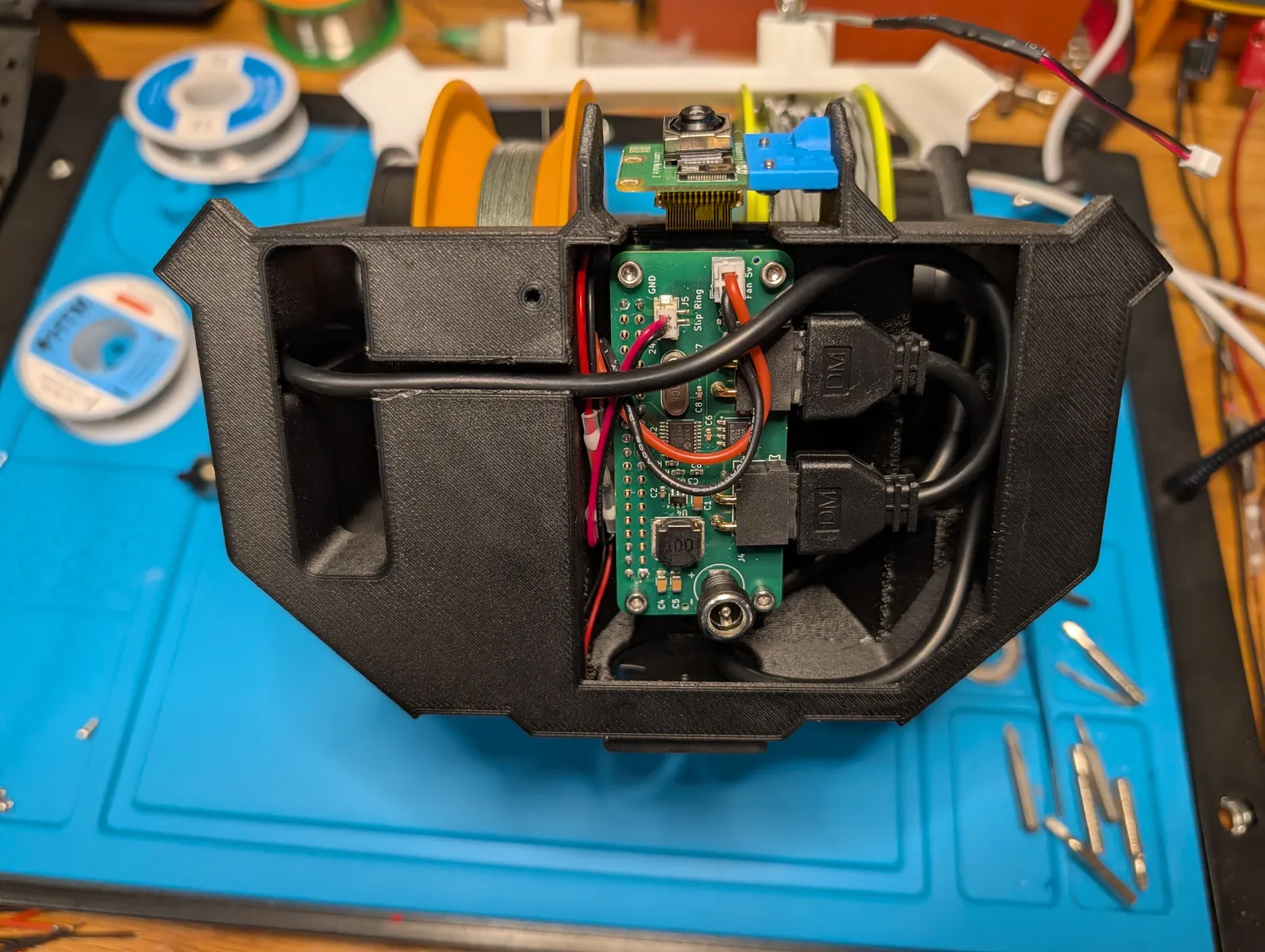
Finally, make sure the black motor cables are tucked away properly in the cavity under the anchor.
The anchor is now finished.
Create the Eyelets
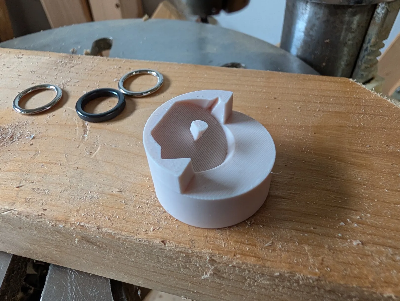
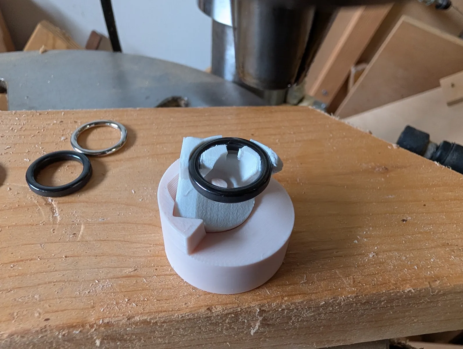
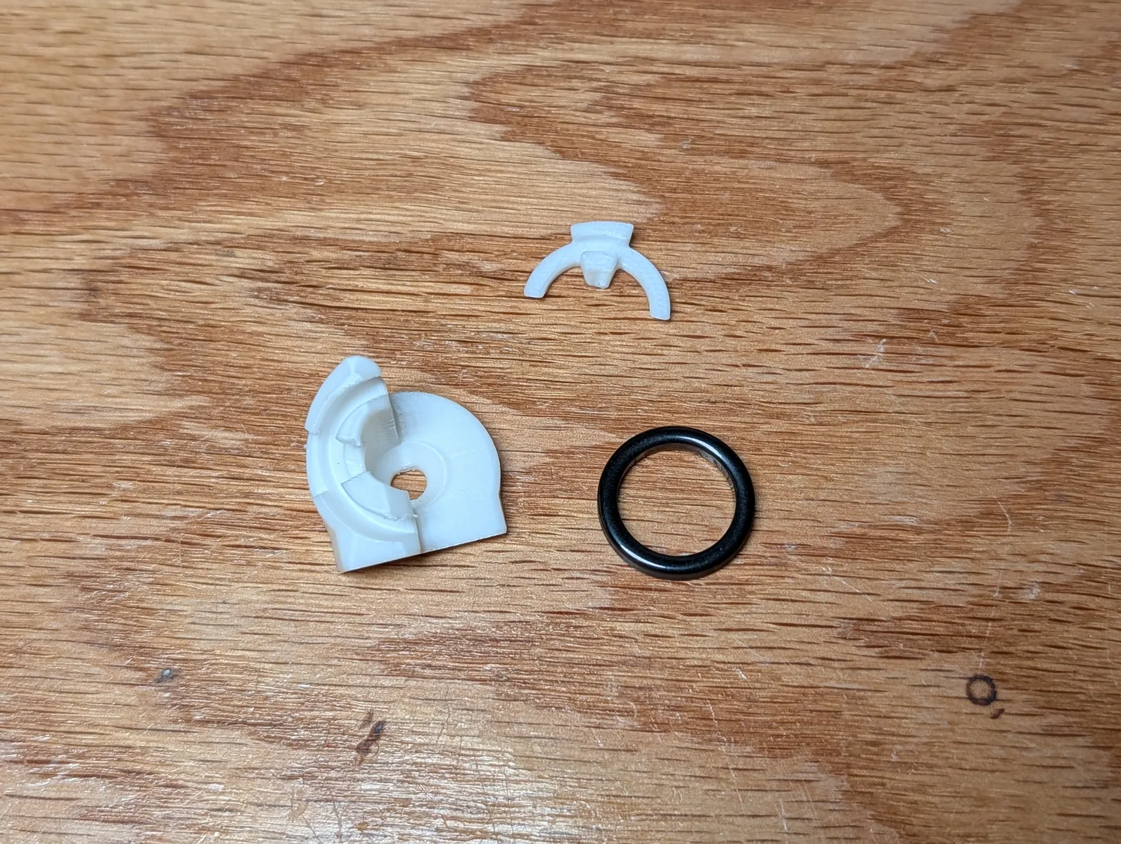
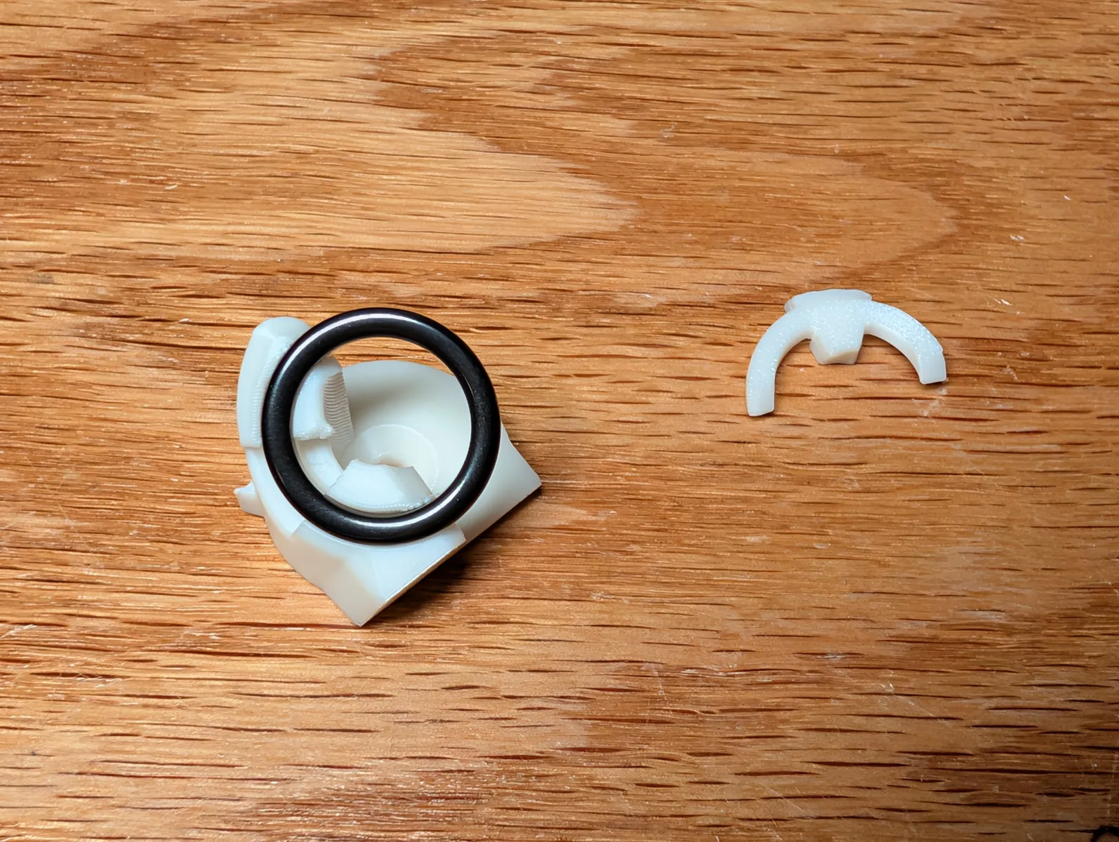
Create two eyelets. Print the body on the flat edge on the lower left side, for strength. print two retainers. Press a size 20 Alconite ring into the ring slot. Put a drop of superglue into the remaining space, and press on the retainer with a coin and something to squeeze it with such as a drill press or vice
The strongest way to make the eyelet is with some kind of press, like a drill press or vice. Print Extras/Eyelet - vice block.stl and set the eyelet body into it so the little arrow sits in the corresponding slot. this makes the ring paralell with the jig's back face. Assemble the stack as:
Body - glue - ring - glue - retainer - coin
And press the whole thing tight. Remove the coin before it sticks.


Complete!
Refer to the Unboxing and Installation page when you are ready to mount it in a room.